Powering the Loudspeaker
Amplifier Selection
It is important that the appropriate amplifier be used for a specific loudspeaker to avoid accidental driver damage.
Underpowered amplifiers will clip easily, sending a highly distorted signal to the speaker. This distorted signal has a
far greater density of energy than normal program and will “burn out” drivers quickly.
Note:
Be certain that the total impedance of all interconnected speakers is not lower than the am-
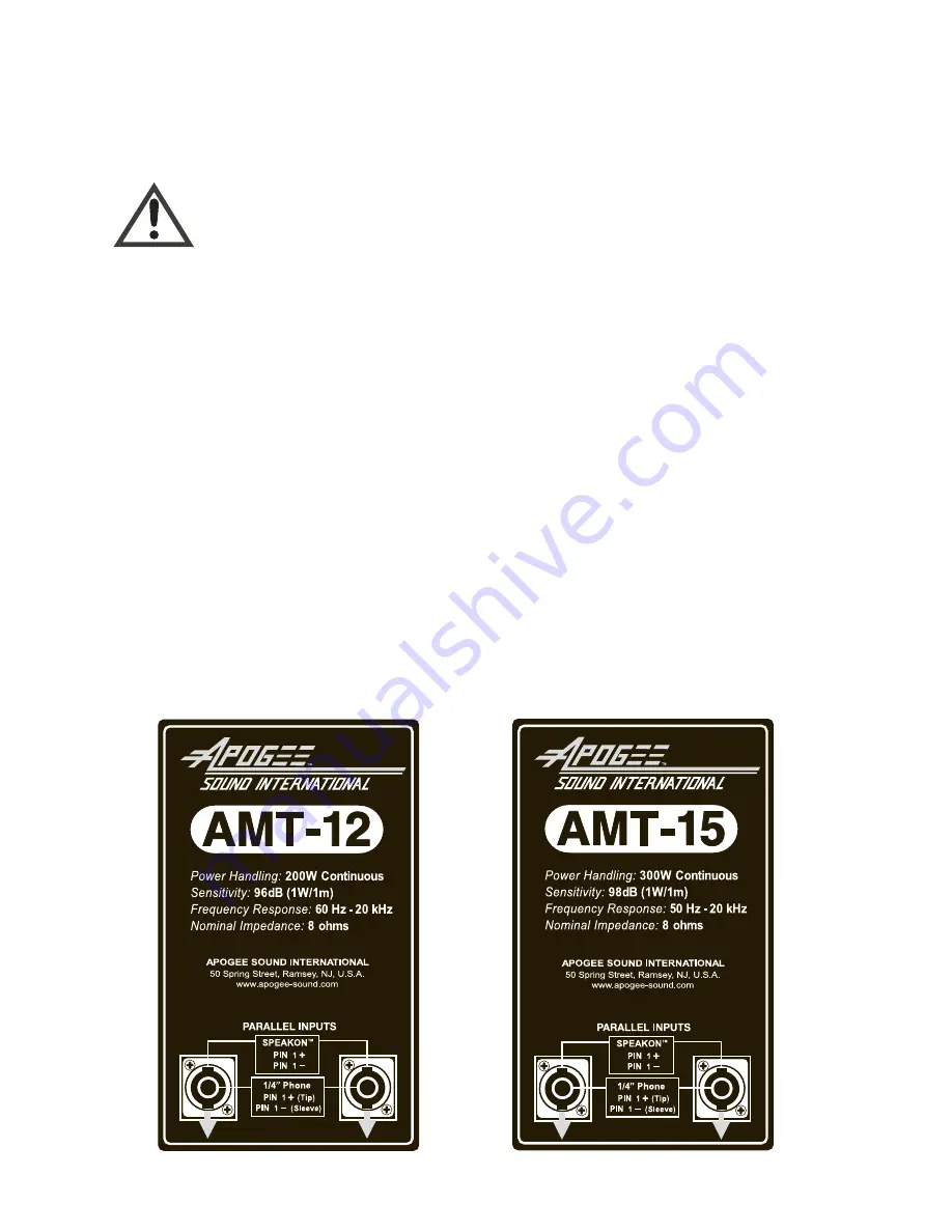
plifier’s minimum rated impedance. The AMT-
1
2 and AMT-
1
5 are 8-ohm speakers.
Wire Selection
Good quality speaker cable of the appropriate gauge is a worthwhile investment. Not all of the power generated by
your amplifier is delivered to your loudspeakers. Some power is lost as heat in the speaker cable. While this heat is
rarely enough to be a fire hazard, it can reduce a significant amount of amplifier power delivered to the loudspeak-
ers. In addition to loudspeakers not reaching their full potential loudness, undersized wire will also decrease the
woofers’ ability to respond accurately to transients, leaving the bass response loose and inarticulate.
The appropriate wire size depends on the distance between the amplifier and the speaker and the final combined
impedance of the speaker or speakers at the end of the cable run. Here is a list of recommended wire gauges:
Distance from Amp to
AMT Speaker
8 Ohms
(
1
Speaker)
4 Ohms
(2 Speakers)
50 Feet
1
6 AWG
1
6 AWG
1
00 Feet
1
4 AWG
1
2 AWG
200 Feet
1
2 AWG
1
0 AWG
400 Feet
1
0 AWG
8 AWG
Input Panel
The AMT-
1
2 and AMT-
1
5 use combination Speakon-type plus
1
/4" Phone-type connectors. Each AMT speaker has a
pair of these connectors wired in parallel, so that a second speaker can be connected to the first speaker if required.
AMT-
1
2 Panel
AMT-
1
5 Panel
3


