3
2
OPERATION INSTRUCTIONS
2.1
Safety Precaution
2.1.1
The current carrying circuits connected with mains power 220 V are a source of
potential hazard.
2.1.2
Measures for Safety:
1)
Do periodically inspect proper RIP grounding;
2)
Regularly ensure that the nominal of the fuse is the same as specified in operation
documentation;
3)
Never open the RIP unless AC line is shut off.
2.1.3
While operating, the RIP must be grounded properly to protect a person against
electric shock in accordance with protection Class I as per GOST R IEC 60950-2002.
2.1.4
Do shut off AC line power prior to mounting, installing or maintaining the RIP.
2.1.5
Only qualified staff certified with the third or higher safety qualification level can
mount and maintain the RIP.
CAUTION! Connecting the RIP to the mains utility power please KEEP UP the
correct coupling of LINE and NEUTRAL TERMINALS in agreement with the picture
located inside the cabinet closely to power terminal block.
2.2
Mounting and Preparing for Operation
2.2.1
The RIP is to be installed on walls or other structures in the protected premises in
places protected against atmospheric precipitations, mechanical damage, and unauthorized
access.
2.2.2
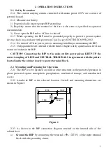
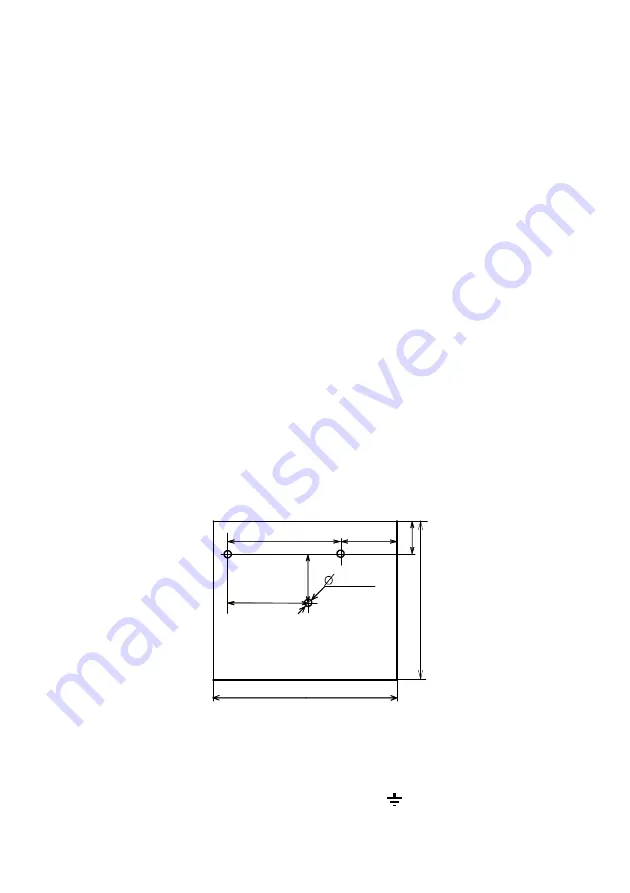
Attach the RIP at the selected location. Overall and mounting dimensions are
shown in Figure 1.
1
4
0
2 2 0
2
7
0
3 4 0
5
1 5 4
1 0 0
*
3
holes
1
5
Figure 1
2.2.3
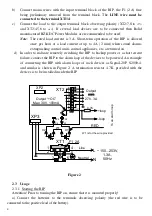
As shown in the RIP connection diagram attached on the internal side of the
cabinet door:
a)
Ground the RIP
by connecting the terminal «
» (XT1/5) of the input terminal
block with the grounding circuit;


