background image


                           Orion ISS 

This  Installation  Manual  contains  the  instructions  that  must  be  followed  for  proper  installation 
and commissioning the S2000-IPDL detector. 
The detector is described and the rules to adjust and operate it are discussed in the User’s 
Manual  (which  can  be  found  at  the  site  of  the  Bolid  Company 

http://bolid.ru

  in  the  section 

PRODUCTS at the page of S2000-IPDL). 

1  SAFETY PRECAUTION 


-

  The detector is a source of danger neither for human nor for protected material 

assets (including the emergency situations). 

-

  The  design  and  circuitry  of  the  detector  ensure  its  fire  safety  during  operation 

(including emergency operation). 

-

  As  to  methods  of  human  protection  against  electric  shock,  the  detector  meets 

the requirements of Class III as per Russian GOST 12.2.007.0. 

-

  In  terms  of  voltage  values,  the  detector  is  not  dangerous  to  human  life  and 

health, but during repair, inspection, installation, and operation it is necessary to 
comply  with  safety  measures  in  accordance  with  Regulations  for  Operation  of 
Consumers’  Electrical  Installations  and  Safety  Rules  for  Operation  of 
Consumers’ Electrical Installations. 

-

  While  installing  and  maintaining  the  detector  please  comply  with  the  rules  for 

working at heights. 

2  MOUNTING 

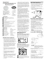
2.1  The units of the detector should be attached to the building structures generally with the 
help of mounting kits supplied: 

Kit No.1:  Designed to attach the transceiver unit and to fasten the housing additionally (if 
necessary) on completing commissioning. 

Kit No.2:  Designed  for  attaching  an  S-Type  (small)  reflector  or  a  remote  indicator  and 
control unit. 

Kit No.3:  For an XS-Type (extra small) reflector. 

Kit No.4:  For an L-Type (large) reflector. 

In  specific  situations  (for  example,  when  the  detector  components  can  be  fastened  only  by 
means  of  threaded  joints)  another  fixture  elements  can  be  used.  Anyway,  it  is  necessary  to 
provide reliable fastening without gaps, drifting, and any motion of the detector’s elements while 
in operation. 

Addressable 

Reflective 

Beam Smoke Detector 


S2000-IPDL 

Installation Manual 


Summary of Contents for S2000-IPDL

Page 1: ... necessary to comply with safety measures in accordance with Regulations for Operation of Consumers Electrical Installations and Safety Rules for Operation of Consumers Electrical Installations While installing and maintaining the detector please comply with the rules for working at heights 2 MOUNTING 2 1 The units of the detector should be attached to the building structures generally with the he...

Page 2: ...he detector enable connecting wires with cross section area 0 2 to 1 5 sq mm wire diameter 0 5 to 1 3 mm If wires of 0 8 mm diameter or less are used then their ends shall be looped 2 8 The housing of the transceiver unit can be removed if only there are no locking screws in the latches at the top and the bottom of the housing To remove the housing release both the latches pressing on them and pul...

Page 3: ...0 m Range 30 to 120 m 25 to 100 m 20 to 80 m S2000 IPDL Transceiver Mounting Kit 5 to 120 m Reflector Four elements max Mounting Kit Rotated by 90 Remote Indicator and Control Unit Rotated by 90 S Type Reflector XS Type Reflector 1 Dimensions for information 2 The distance between Transceiver Unit and Remote Indicator and Control Unit should not exceed 30 m ...

Page 4: ... at least 5 second until the red indicator illuminates The panel PC shall display the events of loss of communication with the device assigned with an old address and finding a device with the new address If several devices were assigned with equal addresses set then there will be no messages about loss of communications for old addresses 4 3 If however it is necessary to change the detector addre...

Page 5: ... second one If you failed to alter this performance then with great probability the detector is improper 5 1 6 If the detector exits the alignment mode normally it shall enter in the Norm state indicating this by red flashing once per four seconds 5 1 7 Arm the detector 5 1 8 Press the TROUBLE button on the detector s board and observe fast flashing with amber Trouble in Progress followed by flash...

Page 6: ... after exiting the alignment mode Норма Norm with Switched from time to time with green flashes Establishing of the Test status after pressing the relevant button with amber flashes Establishing of the Trouble status after pressing the relevant button with white flashes Trouble in Progress Conditions for some Trouble status have occurred but this status has not yet been established Набор Неис Trou...

Page 7: ...obscuration for the reflecting surface and moreover L Type reflectors are equipped with an additional scale at their lower edges which is to be used when the reflectors are arranged with two ones in a row 4 2 2 2 Since the S2000 IPDL is a single ended detector and optical beam crosses the monitored area twice then for simulating the beam degradation by a required value the percentage of obscuratio...

Page 8: ...nt buttons incorporated in remote control unit and duplicated in the detector 4 2 3 2 The relevant button TEST or TROUBLE shall be pressed and held pressed at least for five seconds 6 GETTING STARTED In order the detector to operate under a polling loop controller in an Orion ISS it should be assigned to a polling loop address and relevant settings should be carried out see User s Manual ...

Reviews: