background image

14 


assigned to two or more devices. To set the unit address, send a relevant command from the network 
controller  specifying  an  address  to  be  assigned  to  the  first  relay.  Then  within  5 min  perform  the 
following combination of presses on the unit tamper switch: three long ones (> 1 sec) and one short 
press. The network controller shall display events about loss of communication with the device with 
the  old  addresses  and  connecting  with devices with  the new  addresses.  For  the  case  of  two  or more 
devices which have the same addresses, there will be no messages about missing the devices with old 
addresses. 

If  you  need  to  change  the  unit  addresses  which  are  known,  send  the  Change  Device  Address


command from the control panel or the PC specifying the current address and the new address as the 
parameters.  The  network  controller shall  display  messages  about disconnecting  the devices  with the 
old addresses followed by messages about detecting the devices with newly set addresses. 

Note

!

 If the unit is assigned to the address 127, then the second relay  (address) fails to be used 

because 127 is the maximum value of address in the system. 

 
Defining parameters: 
Configuration parameters of the unit are stored in the memory of the polling loop controller; they 

are  to  be  defined  on  the  Outputs  tab  of  UProg  Configuration  Tool.  The  list  of  the  configuration 
parameters is presented in Table 2.2.1. 

Specific values of the configuration parameters to be defined are to be selected depending on the 

type of the actuating devices connected to the unit and the requirements for their operation in scope 
of the specific project. 

To  have  more  details  on  the  purpose  and  assigning  configuration  parameters  of  the  unit,  please 

refer to the polling loop controller operation documentation. 


Table 2.2.1

 – Configuration Parameters of the Unit


Parameter 

Description 

Range 

Default Value 

Control Program 

Defines  how  the 

output 

is  to  be 

operated 

0 – 53 

Operation Time 

The  time  for  a time-limited  program to 
operate for 

0…8160 s 

(up to 2 h 16 min) 

with 0.125s increment  

(8160 s: Always On) 

60 s 

Activation Delay 

The time after which the related control 
program  shall  be  run.  Used  in  the 
programs 1…8, 11, 12, 17…53 

0…8160 s 

(up to 2 h 16 min) 

with 0.125s increment 

AND / OR Logic 

Condition  for  turning  the  programs 

36


and 

37

  on  (off)  when  the 

output

  is 

related  to  several 

inputs

  of  Type 

10

  or 

Type 

15


0 – OR 

1 – AND 

0 (OR) 

Temperature 

Increased 

Threshold 

The  temperature  value  on  reaching 
which  the 

output

  is  to  be 

turned  on


(

off

) for the control program 

36

 (

37

Minus 55…+125°

С


22 

Temperature 

Decreased 

Threshold 

The  temperature  value  at  which  the 

output

 is 

turned off

 (

on

) for the control 

program 

36

 (

37

Minus 55…+125 °

С


20 

Summary of Contents for S2000-SP2

Page 1: ...ADDRESSABLE TWO OUTPUT ALARM ACTUATING UNIT S2000 SP2 Rev 02 User s Manual ...

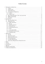
Page 2: ... 9 2 2 1 Safety Precautions 9 2 2 2 Design 9 2 2 3 Mounting the Unit 10 2 2 4 Wiring the Unit 12 2 2 5 Programming the Unit 13 2 2 6 Usage 15 2 2 7 Testing Operability 15 2 2 8 Extreme Situation Actions 16 2 2 9 Troubleshooting 16 3 Maintenance 17 3 1 General 17 3 2 Safety Precautions 17 3 3 Maintenance Procedures 17 3 4 Testing Operability 17 3 5 Technical Examination 17 3 6 Preservation Depreser...

Page 3: ...the personnel who have studied this manual are allowed to operation activities All activities on mounting start up programming and testing shall be performed in compliance with the requirements of the regulatory documentation in force at the place of operation Abbreviations CIE Control and Indicating Equipment ISS Integrated Security System PL Multiplex Addressable Polling Loop ...

Page 4: ...ms The unit is used with an S2000 KDL or S2000 KDL 2I polling loop controller under an S2000M control panel or Sirius Fire Alarm Control Panel or one of their modifications as a component of modular control and indicating equipment in such system as a fire intrusion panic alarm system a voice fire alarm and evacuation system a fire suppression and smoke control system an access control system a CC...

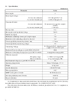
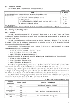
Page 5: ...y of the executive part Enclosure Protection Degree as per GOST 14254 2015 IP40 Resistance to mechanical exposure as per OST 25 1099 83 Arrangement Category III Vibration exposure Frequency range Max acceleration 1 35 Hz for Category III 0 5 g for Category III Environmental category as per OST 25 1099 83 O3 Operating temperatures Minus 30 through 55 С Weight 0 2 kg max Overall dimensions 102 107 3...

Page 6: ...relatively to the 0V terminal Normal between minus 0 15 V and minus 1 125 V Open Circuit Fault less than minus 1 125 V Short Circuit Fault higher than minus 0 15 V Status of a switched on monitored circuit is defined by the value of monitored circuit current Normal between 5 mA and 3 A Open Circuit Fault less than 5 mA Short Circuit Fault higher than 3 A Note If an output while being switched on i...

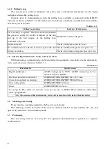
Page 7: ...1 5 Measuring Instruments Tools and Accessories While mounting commissioning and maintaining the equipment one should use the instruments tools and accessories shown in Table 1 5 1 Table 1 5 1 Instrument Specifications Digital multimeter AC DC voltage up to 500 V AC DC current up to 5 A resistance up to 2 MOhm Flat head insulated screwdriver ZUBR ELECTRO EXPERT SL 3 0х75 mm Cross slot insulated sc...

Page 8: ...g emergency operation in accordance with Russian standards GOST 12 2 007 0 75 and GOST 12 1 004 91 The unit has no circuits under a hazardous voltage Do SHUT OFF power from the equipment before mounting installing and maintaining this one Installation and maintenance of the unit shall be carried out by professionals qualified for Accident Prevention of Class II or higher 2 2 2 Design The unit is c...

Page 9: ...acently vertical and horizontal distances between them shall be at least 10 mm each The design of the unit doesn t provide its operation in aggressive and or dusty environments as well as in explosion hazardous and flammable premises The unit shall be installed at a height suitable for operating and maintenance Installation and maintenance of the unit shall be carried out by professionals qualifie...

Page 10: ...nnect electric wires to the unit as per the project design documentation and the connection diagram Close the unit with its cover To dismantle the unit please follow all the steps in the reverse order Mounting on a DIN rail Install the unit on the DIN rail Remove the cover from the unit Connect electric wires to the unit as per the project design documentation and the connection diagram Close the ...

Page 11: ...stems or equipment in explosion protected housing load connection modules can be installed in close vicinity from them 4 If an output is not in use one can replace load connection module with a 510 Ohm 1 2W resistor Figure 2 2 5 General Schematic for Connecting the Unit Connecting to fixed fire fighting systems should be conducted in accordance with the schematic in Figure 2 2 6 The length of wire...

Page 12: ... so on can be connected in parallel across a single output if the following requirements are met In the quiescent mode the appliances are turned off The total current per the output doesn t exceed the maximum allowed one 3 A Mounting is conducted in accordance with the schematic shown in Figure 2 2 7 Figure 2 2 7 The Diagram for Connecting Several Normally Turned Off Sirens or Light Signs to a Sin...

Page 13: ...controller they are to be defined on the Outputs tab of UProg Configuration Tool The list of the configuration parameters is presented in Table 2 2 1 Specific values of the configuration parameters to be defined are to be selected depending on the type of the actuating devices connected to the unit and the requirements for their operation in scope of the specific project To have more details on th...

Page 14: ...To change configuration parameters please use UProg utility v 4 1 0 26 2 2 6 Usage The unit is operated under an S2000 KDL polling loop controller and S2000M control panel or Sirius fire alarm control panel All operating conditions control program time to operate delay before operating the output are defined by configuration parameters of the equipment mentioned above To get information how to def...

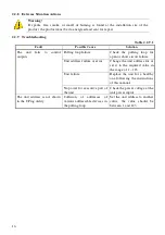
Page 15: ...it failure Replace the unit for a healthy one following the instructions of this manual No power for executive part of the unit Check the power voltage at the unit power inputs The unit address is not shown in the UProg utility Collision of addresses of various addressable devices in the polling loop Set the unit address to another value the value should be between 1 and 123 Warning If sparks fire...

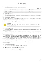
Page 16: ...oupled with automated fire fighting equipment shall be disconnected from the outputs of the unit and be replaced with the simulators similar in the load current After applying power to the unit the built in indicator READY start lighting steady until the moment the polling loop controller polls the given address Then the indicator goes to flash slowly Remove the cover from the unit and ensure that...

Page 17: ...transport container at ambient temperatures minus 50 up to 55 С and relative humidity up to 95 at 35 С 7 Disposal The unit can be disposed of considering that there are no toxic components in it The content of precious materials doesn t require accountability for storage retirement and disposal Clause 1 2 of GOST 2 608 78 The content of non ferrous metals does not require accountability for retire...

Page 18: ...ut Alarm Actuating Unit meets the requirements of Technical Regulations of Custom Union Electromagnetic Compatibility of Technical Equipment TR CU 020 2011 It is covered by the conformity declaration ЕАЭС No RU Д RU HP15 B 06633 20 Production of S2000 SP2 rev 02 is awarded with the conformity certificate GOST R ISO 9001 The certificate can be found online at the website http bolid ru in the sectio...

Reviews: