Addressable Radio Link System
www.bolid.ru
62
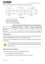
Figure 10-9 shows the variants of connecting monitored circuits to the detector.
Figure 10-9
R
EOL
= 5.6
К
; R1 = 2.4
К
; R2 = 5.6
К
;
D1 is for a fire normally closed detector;
D2 is for a fire normally open detector;
D3 is for an intrusion normally open detector;
D4 is for an intrusion normally closed detector.
Table 10-17. Monitored Circuit Resistance Values and Their ATD Values
Short Circuit
Alarm 1
Norm
Alarm 2
Open Circuit
Resistance, K
0…0.2
1…2.8
4…7
10…20
40…
∞
ATD value
11…32
88…149
170…198
212…232
243…255
Defeat Protection
The Defeat Protection option is designed to detect attempts of penetration into protected premises by
defeating the S2000R-SMK with the help of an external powerful magnet.
This option is to be enabled/disabled in the configuration of the polling loop controller (see Section 8
of this Manual).
Mounting Location Considerations
Considering the mounting location for the S2000R-SMK, please follow:
The instructions from Section 9 of this Manual.
All your applicable local codes, standards, regulations, and ordinances.
In order Defeat Protection to operate correctly, the Magnet must not be fitted closer than
5 mm to the detector. Otherwise, both reed switch contacts can trigger and a relevant
alarm will be sent

