background image

User Manual


13 

5.3 Main Menu


If system interface is lock, please firstly input password to unlock before entering into [Main Menu]. Details 

please refer to section 5.4– Menu Lock. 

5.3.1 Camera Set     


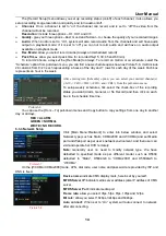
Display time while in live view: allows you setup display time in the live mode. 


Display  time  while  recording:  the  option  is  set  to  ON,  the  display  time  while  recording  will  appear  in  the  screen 

when play backing record; set to Off, the display time while recording disappear in the screen. 


2

If you want to cancel the modification, click [Exit] button to exit the menu. 

3

When clicking [DEFAULT] button, all system values will be reset to default value. 

4

System default value indicates the value pre-set at the factory. 


5.3.2 Record Set 

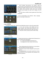
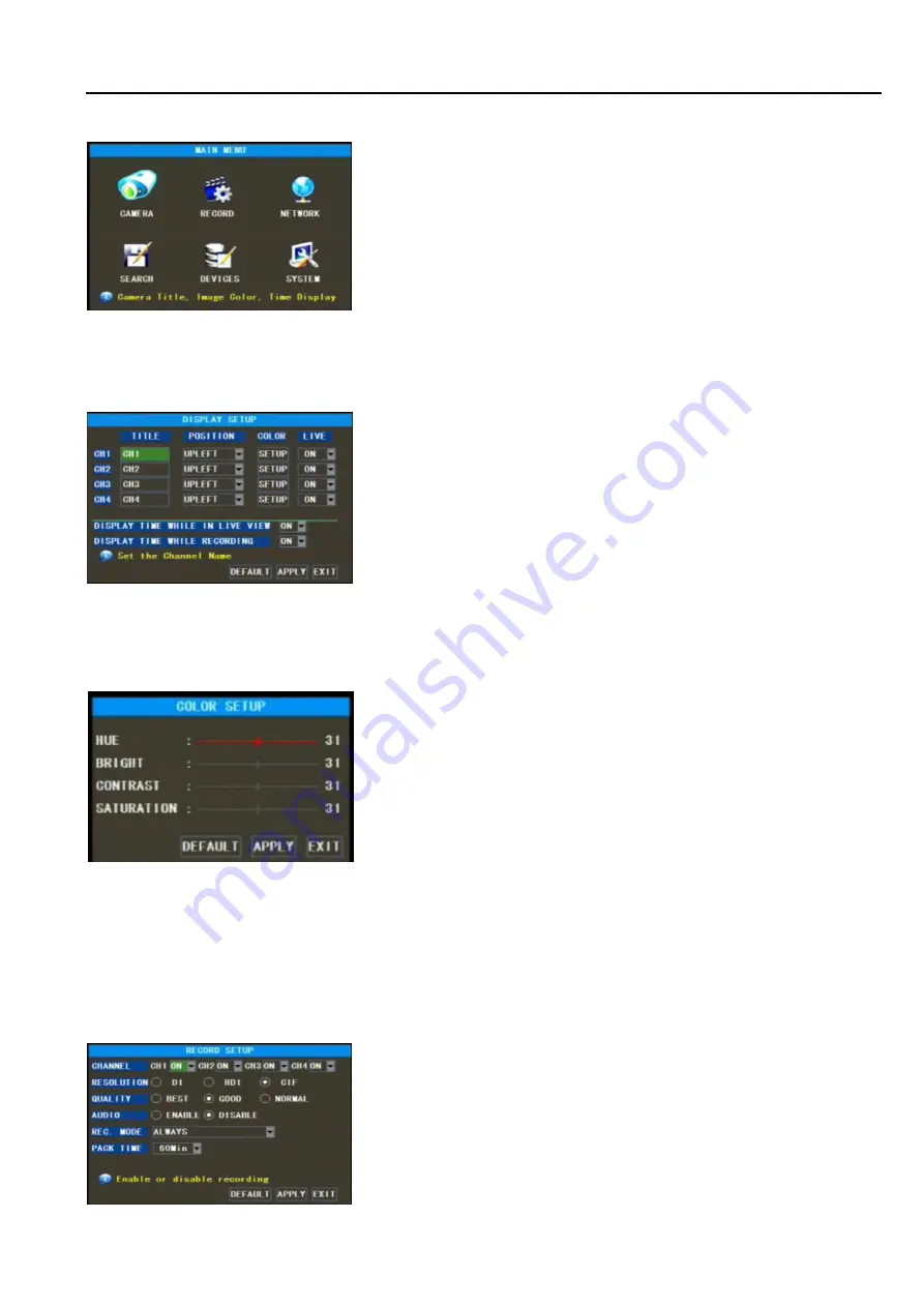
Click [Main Menu

Record Setup] option to enter into the interface shown as Picture 5-5. 


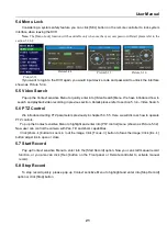
In  Main  Interface  mode,  click  right  key  of  mouse  to  pop  up 

Context Sensitive Menu, and then highlight and select [Main menu] 

item to enter into Main menu. Now user can freely set parameters 

for [Camera], [Record], [Network], [Search], [Device] and [System] 

as per user’s needs.   

The  [Record  Setup]  menu  allows  you  set  up  recording  status 

(on/off) of each channel, it also allows you setup recording image 

resolution and quality, and turns audio on/off.


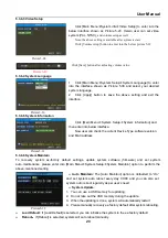
Below is the Color Menu where you can adjust image brightness, 

saturation, contrast and hue parameters of each channel.(shown as 

picture 5-4). 

Friendly Reminder:   

1

The modifications will be available only when clicking [APPLY] 

button on the bottom of the sub-menu windows and being prompted 

to save and then clicking [ok] button. 

Go  to  [Main  Menu

Camera]  to  set  up  the  title  and  Position  of  each 

channel  (Shown  as  Picture  5-3).  You  can  also  adjust  image  brightness, 

saturation, and contrast and hue settings of each channel after entering into 

[Color]  menu  and  set  up  whether  each  channel  can  be  previewed  or  not 

under Live display and/or Record mode. 


Please  note  that  the  title  of  each  channel  support  up  to  eight 

characters. 

Picture5-4 

Picture5-2 

Picture5-3 

Picture5-5 

Summary of Contents for SVR9000S-T4MO

Page 1: ...1 ...

Page 2: ... 3 I O cable 6 2 3 4 Alarm I O 7 2 3 5 Speed sensor 7 Chapter3 Connecting DVR 8 3 1 The device installation 8 3 2 Removeable HDD installation 9 3 3 Connecting Power Supply 10 3 4 Connecting Camera and Monitor 10 3 5 Connecting GPS Antenna Optional 10 3 6 Connecting 3G Mould Antenna Optional 10 3 7 Getting Started 10 Chapter 4 Starting the system 11 4 1 System Initialization 11 4 2 Main Interface 1...

Page 3: ...deo Setup 20 5 3 6 4 System Language 20 5 3 6 5 System Information 20 5 3 6 6 System Maintain 20 5 4 Menu Lock 21 5 5 Video Search 21 5 6 PTZ Control 21 5 7 Start Record 21 5 8 Stop Record 21 Chapter 6 EXT2 Drive 22 6 1 System requirement 22 6 2 EXT2 Setup 22 6 3 Record export software 23 Chapter 7 Net Viewer Program 25 7 1 How to install Net Viewer program 25 7 2 Off line working 25 Chapter 8 Spe...

Page 4: ... 6 Unplug this equipment and refer all servicing to qualified service personnel under the following condition When the equipment exhibits a distinct change in performance or When liquid is spilled or objects have fallen into the equipment 7 Protect the power cord from being walked on or pinched particularly at plugs convenience receptacles and the point where they exit from the equipment 8 Operato...

Page 5: ...port record on schedule when car ignition is on Support record on 4 CH alarm and DVR auto switch on while opening the car door Support Motion detection record 1 4 Data storage and backup Retractable HDD box easy to install system support a internal 2 5 SATA HDD With USB2 0 port and support backup record and update software via U flash disk or removable hard disk Support Retractable HDD directly co...

Page 6: ...ht on when video loss is triggered f GPS Indicator light on when installing GPS mould and have no received GPS signal and light flash when received GPS signal g ALM Indicator light on when any alarm is triggered h Net Indicator light on when wireless Net is installed and on the status of working i ERR Indicator light on when error occurs j HEAT Indicator light on when heat mould is working Optiona...

Page 7: ...tion signal input connected to car power level The 6 pin plug will be connected to power supply jack of rear panel Red and black wires connected to car battery and respectively yellow wire to ignition wire Reminder 1 Make sure the power supply is between 9V and 32V to avoid the device damage due to higher voltage 2 It is very import for you to make the wires insolated 3 Yellow wire must be connect...

Page 8: ...Black BNC port 9 CH1 Audio input White BNC port 10 CH1 Video input Black BNC port 11 12 Monitor 12 V power supply output Red Positive pole Black Negative pole 13 14 CH4 Camera 12V power supply output Red Positive pole Black Negative pole 15 16 CH3 Camera 12V power supply output Red Positive pole Black Negative pole 17 18 CH2 Camera 12V power supply output Red Positive pole Black Negative pole 19 2...

Page 9: ...85A 15 Pin RS485B Alarm input SENSOR1 4 4 CH alarm input Alarm input SENSOR5 8 4 CH alarm input can act as emergency button Alarm output ALARM0 1 2 CH alarm output Speed Sensor SPEED Speed sensor connect to speed pulse Note Note Note Note SENSOR1 8 is off or connected to GND they are acted as low level ...

Page 10: ...to pulse output of car sensor 2 If speed meter have pulse signal output the speed sensor input of camera can directly connected to the ouput port of speed meter If speed meter has no pulse signal output that means you need to connect pulse signal output of speed sensor to the speed meter input 3 Camera will receive pulse signal from speed sensor through Menu setting 4 How to calculate pulse count ...

Page 11: ... Channel select CH1 CH4 numeric key 0 5 9 numeric key numeric key numeric key numeric key ALL Multiple CH display Multiple CH display Multiple CH display Multiple CH display Menu Enter Main Menu Exit Enter Main Menu Exit Enter Main Menu Exit Enter Main Menu Exit Up direction arrow Up direction arrow Up direction arrow Up direction arrow Down direction arrow Down direction arrow Down direction arro...

Page 12: ...D installation Please follow the below steps to install the HDD 1 Take out removable HDD from the HDD box 2 Loosen the screw and remove PCB board 3 Remove the upper cover of HDD box 4 Put the HDD on the anti vibration rack and connect SATA port of data cable to HDD 5 Fix the HDD to the HDD box with screws 6 Install the upper cover back HDD box with screws 7 Tighten the PCB board back HDD box with ...

Page 13: ...ely camera and monitor to the corresponding port on the rear panel shown as section 2 2 Rear Panel 3 5 Connecting GPS Antenna Optional Connect GPS Antenna to the GPS port on the rear panel shown as section 2 2 Rear Panel Please make sure the front of GPS Antenna have no any blockages to avoid affect its signal receive and transmittal 3 6 Connecting 3G Mould Antenna Optional Connect 3G Mould Antenn...

Page 14: ...xt Sensitive menu Note If DVR is not connected to Hard Driver H Character will appear in the screen MDVR will automatically restart after two minutes under the default mode If you want to close the Auto restart after two minutes function please refer to Section 5 2 5 1 HD management Connect the power cable of DVR to power supply and press the Power button you will see the initialization screen sho...

Page 15: ...Menu Now you could perform parameter setting and control for Main Menu Menu Lock Video Search Start Record Stop Record and PIP Mode etc Main Menu Rec Search Camera Record HDD Manage Alarm Setting Motion Detect System User password System Information Language Select System Maintenance Video Setting Time Setting Device Management Network Vehicle function Exit PTZ Setting Picture5 1 ...

Page 16: ...then highlight and select Main menu item to enter into Main menu Now user can freely set parameters for Camera Record Network Search Device and System as per user s needs The Record Setup menu allows you set up recording status on off of each channel it also allows you setup recording image resolution and quality and turns audio on off Below is the Color Menu where you can adjust image brightness ...

Page 17: ...use the From To pull down menus and Copy button to copy settings from one day to another day or all days RED ALARM GREEN NORMAL WHITE NO RECORD 5 3 3 Network Setup On the WCDMA CDMA2000 mode APN dial code user name and password are provided by ISP and DNS is fixed After entering into Schedule option you can select your desired channel s All CH1 CH2 CH3 and CH4 from the pull down menu To setup week...

Page 18: ...on to enter into the below window illustrated in picture 5 12 Picture5 11 Time Search In the Video Search screen user can search for a specific date and time for a recording and view it in Playback mode This is useful for hunting a specific recording of an incident if you know the date and time it occurred The DVR supports 4 CH playback simultaneously Select a desired date time and click Search bu...

Page 19: ...set to Reboot the DVR will auto reboot after two minutes when system have detected current HDD is not properly installed or not formatted if set to IGNORE the DVR will cancel the HDD Status status of the currently installed hard drive If the hard is not installed properly you will see a message saying NO DISK FOUND Total space Total size of the hard drive currently installed Free space Total free ...

Page 20: ...triggered once sensor level is high on the contrary when set to High sensor level is low when set to Off there are no alarm triggered HDD Loss When the option is set to ON buzzer will release the alarm sound and H mark will appear on the screen once HDD loss or HDD not available when set to OFF H character still appear on the screen but have no alarm sound heard HDD space When the option is set to...

Page 21: ...agement Motion Detection to enter into the below interface shown as Picture 5 19 Channel Status Video motion detection can be turned on or off for each camera SENSITIVITY This option allows you to set sensitivity level of motion detection from 1 to 4 with 4 being the most sensitive List 5 1 Picture5 20 MD Area This option allows you setup the MD area for the channel you wish to be sensitive to mot...

Page 22: ...ion 2 Click Apply button to save and exit current setting When enabling password to On first time you can set User Password and Admin Password respectively Password is consist of numeric character 0 9 with a specific length 6 bit Friendly Reminder User only has a permission to access Video Search menu But Administrator has full authority over Main Menu operations Enter into Main menu Device PTZ Se...

Page 23: ...tem information and then enter into below interface Now user can check the current Device Type software version and MAC address Auto Maintain The Auto Maintain option is defaulted to On and set system auto reboot every day 00 00 and you can also set system auto reboot regularly as per user s need System Update 1 You can use a USB memory for updating 2 Do not take out the USB memory during the upda...

Page 24: ...PTZ Control We introduced setting PTZ parameters previously in chapter 5 3 5 5 Here we will discuss how to operate PTZ controls Pop up the Context sensitive Menu to highlight and enter into PTZ control menu shown as Picture 5 32 Now user can control the camera with Pan Tilt and Zoom capabilities Click Zoom button to zoom in out the image Click Focus button to focus the image Click Iris button adju...

Page 25: ...onfiguration CPU Pentium 4 processor 2 0GHz or above Memory 1GB or above 6 2 EXT2 Setup It is recommended that you close all other application before the setup Please follow up the below steps for installation 1 Enter into the HDD Tool file 2 and then double click to run the Ext2setup exe file and this will install ext2 on your computer 3 Click Next button to continue 4 Click Install to continue w...

Page 26: ...ote If you still not identify the EXT2 system please install Bak 1 Ext2Fsd program from the provided software CD attached installation instruction on the software CD 6 3 Record export software Due to using special file system we can t read the index documents with nvr format and must export the file via special export software Before exporting please connect HDD box to PC via USB cable and system ...

Page 27: ...ton on the right of Source file column after enter into sub window select the file you want to export 4 Select the targeted route you desire to save from Destination column 5 And then click button to start exporting the record file Note a The processing bar point again single file If you have selected multiple files or all the directory the processing bar will appear in the screen frequently b If ...

Page 28: ...sh the installation step by step 5 Finish the installation processing you will see the interface shown as Picture 7 1 7 2 Off line working Click the Off line button on the right upper corner of the screen shown as Picture 7 1 Enter into the Off line interface shown as Picture7 2 Now you are allowed to playback the backup file Click Add button on the right down corner to pop up the window shown as ...

Page 29: ... Picture 7 7 Picture 7 8 Enter into and select the file you want to playback shown as Picture 7 4 Highlight and open the file you desire to playback shown as Picture 7 5 Now the record file has been added to the interface shown as Picture 7 6 Picture 7 4 Picture 7 5 Picture 7 6 Picture 7 7 Picture 7 8 ...

Page 30: ...f the screen Slide the volume control bar to adjust the volume Select one record file and click Delete button to delete the file Picture 7 9 Click the 264 to AVI button to enter into the interface shown as Picture 7 10 Picture 7 10 Click the button to enter into origin file and target file s route respectively Picture 7 11 Click the Convert button to convert 264 to AVI format shown as Picture 7 12...

Page 31: ...d Slow play frame by frame Alarm I O 4 CH alarm input 2 CH alarm output Alarm Mode Motion detection Sensor Triggered Video Loss HDD full and HDD error USB Port Support removable HDD and U flash disk for backup and U flash disk update Ethernet Interface Support RJ45 Ethernet interface Wireless Network Support wireless video Audio transmission via 3G network Optional GPS Support embedding latitude l...

Page 32: ...is in Play mode pressing Stop button to exit the Play mode and then you can enter into the Record function 7 Q Why the Remote Controller can t work normally A Check if the battery is power off or check if the Remote Controller is broken 8 Q Can we records whilst playing back A Yeah you can do it The system support you records whilst playing back 9 Q Can we erase some recorded file from DVR A Consi...

Page 33: ...Manual 30 8 2 Accessories Optional Remote Controller Software CD User Manual Alarm I O Cable Power Cord Two Keys A V Cable GPS Mould Antenna Optional EVDO Mould Antenna Optional Triple headed USB data cable ...

Page 34: ... guarantee is given as to the correctness of its contents We do not undertake any responsibility for the harms cause by using our product The model of the products in the user s manual only for recognition but these names also perhaps are belong to other company s registered trademark or the copyright The product picture may differ from the actual product only for your reference The accessories wi...

Reviews: