background image

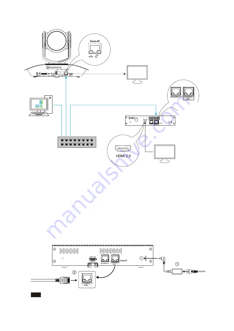
3. Connection Diagram

1 2 3 4 5 6 7 8

Dante AV

PTZ Camera

Two Ethernet ports available, only 

Port 1 supports POE++.

Network Cable Connection (POE    Powered)

PO

E     
po

w

er 

via 

ne

tw

ork 

ca

ble

Network Cable

Direct Camera 

HDMI Output

HDMI Output

Dante 

Controller

POE++ Switch

Display Output Device

Display Output Device

Dante AV Decoder

++

Note: 

. DHCP network configuration is recommended.

 If network does not support DHCP, please manually configure IP details 

on the camera and decoder to match the same gateway.

 Switch Requirement:


·

 Nonblocking Layer 2


·


Green Ethernet must be OFF (Recommend not using Green Ethernet capable switches)


·

 Use reputable "Managed" switches


 ·

 Support QoS with strict priority and 4 queues


·

 IGMP Snooping ON


·


Please refer to product manual at www.bolintechnology.com for IP configuration instructions

++

. Power Adaptor (DC 12V 4A) to power the decoder.

.  When using POE ++ , use IEEE802.3bt certified switch to power this decoder

4. Power on the Decoder

Both DC12V and POE are workable, when powering the camera, DC 12V preferably. 

DC  12V

DC 12V 4A

For Dante AV camera startup tips, please refer to its respective diagram.

Note:


4

++

++

++

++

++

++

Summary of Contents for Dante AV D220

Page 1: ...D a n t e A V D e c o d e r T M Version 1 0 Quick Start Guide Dante AV PTZ Camera Decoder ...

Page 2: ...nte AV video output Thank You Card x 1 Power Cord x 3 Type US EU UK Power Adaptor x 1 Power Cord x 3 Type US EU UK 1 HDMI Cable Mount 1 1 2 3 4 5 VCC CC45RS RJ45 to RS422 Control cable x 1 IN OUT VCC CC45RS Control cable x 1 RJ45 to RS232 BL CM 01 For Decoder BL WM 01 M4 6PW Screw X3 M2 5 3C Screw x 2 M4 6PW Screw x 8 M2 5 3C Screw x 8 M3 8K Screw x 4 M5 12P Screw x 4 8 300mm Cable Tie x 4 HDMI Ca...

Page 3: ...1 2 or 3 on the IR Select to control the camera 1 2 3 4 5 6 7 8 Note Power off the camera prior to changing dial settings Resolution can also be changed via OSD menu once the camera is powered on Camera will follow the latest configured resolution Refer to the camera manual for further detail Infrared Remote control ID please dial it to the desired location Choose 1 when there is only one camera 1 2...

Page 4: ... Network Switch Not included Computer Dante Controller x 1 2 Install Dante Controller Software Dante Controller Download URL https my audinate com support downloads download latest dante software lang zh hans Dante Controller Hardware Requirements CPU Minimum of 1GHz processor Storage At least 512MB Network Card Ethernet connectivity port 1000 Mbps Dante Controller OS Requirements Note 5 Dante AV ...

Page 5: ...and decoder to match the same gateway Switch Requirement Nonblocking Layer 2 Green Ethernet must be OFF Recommend not using Green Ethernet capable switches Use reputable Managed switches Support QoS with strict priority and 4 queues IGMP Snooping ON Please refer to product manual at www bolintechnology com for IP configuration instructions Power Adaptor DC 12V 4A to power the decoder When using POE...

Page 6: ...rmal Error For Dante AV camera startup tips please refer to its respective diagram Note 6 Display Camera Video via Decoder x 1 Click to choose network interface This is mandatory when there are multiple network connectivity methods on the device Configure Dante Interfaces in Unmanaged mode Select the network interface that the Dante Controller Use Shared Dante interface Primary Interface Secondary...

Page 7: ... Multicast Primary v2 Multicast Secondary v1 Multicast Secondary v2 Multicast Dante Dante Follower Leader Disabled N A N A Preferred Leader Enable Sync To External Disabled N A N A N A N A N A N A D10H 02263c D220 0225a2 Dante Controller Video Network View File Devices View Help Routing Device Info Clock Status Network Status Events Primary Leader Clock D220 0225a2 x Device Name Model Name Product...

Page 8: ...ff prior to changing the DIP switch setting When there are multiple DanteAV cameras involved refer to the table above for unique VISCA address to each camera Up to seven unique address can be assigned to cameras at any given time Camera VISCA Address Communication Protocol and Baud Rate Settings Example For VISCA ID 1 with RS422 Protocol and 9600 baud rate then set the DIP switch 1 8 to ON OFF OFF ...

Page 9: ...2082 TECHNOLOGY LLC dba BOLIN TECHNOLOGY ...

Reviews: