background image

0DLQWHQDQFH

%20$*

30

BPR 25/32 - BPR 25/40

4.5

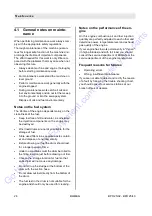
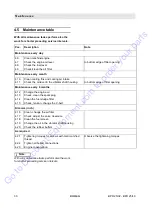
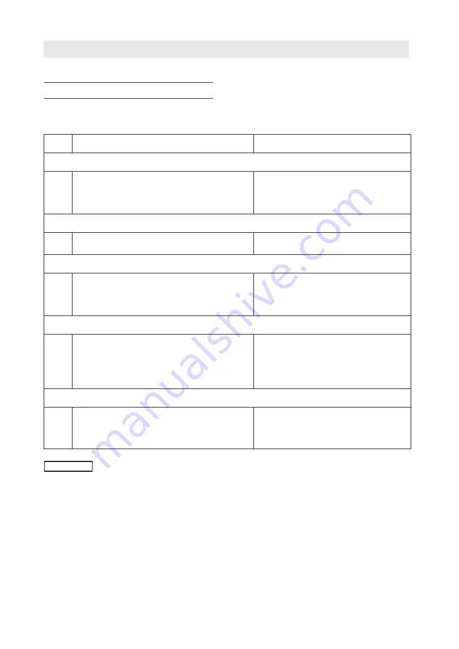
Maintenance table

With all maintenance tasks perform also the 
work for shorter preceding service intervals.

L

Note

With all maintenance tasks perform also the work 
for shorter preceding service intervals.


Pos.

Description

Note

Maintenance every day

4.6

Clean machine/engine

4.7

Check the engine oil level 

to bottom edge of filler opening

4.8

Check the fuel level

4.9

Check/clean the air filter

Maintenance every month

4.10

Clean cooling fins and cooling air intake

4.11

Check the oil level in the vibrator shaft housing 

to bottom edge of filler opening

Maintenance every 6 months

4.12

Change the engine oil

4.13

Check, clean the spark plug

4.14

Clean the fuel sludge filter

4.15

Check, tension, change the V-belt

Dim. mm (inch)

4.16

Clean, change the air filter

4.17

Check, adjust the valve clearance

4.18

Clean the fuel screen

4.19

Change the oil in the vibrator shaft housing

4.20

Check the rubber buffers

As required

4.21

Tightening torques for screws with metric unified 
thread 

Observe the tightening torques

4.22

Tighten all bolted connections

4.23

Engine conservation

Go 

to 

Discount-Equipment.com 

to 

order 

your 

parts

Summary of Contents for BPR 25/32

Page 1: ...uctions Maintenance instructions Catalogue number 35 35 S N 101 730 00 S N 101 730 10 9LEUDWRU SODWH FRPSDFWRU www discount equipment com G o t o D i s c o u n t E q u i p m e n t c o m t o o r d e r y o u r p a r t s ...

Page 2: ...ne needs We sell worldwide for the brands Genie Terex JLG MultiQuip Mikasa Essick Whiteman Mayco Toro Stone Diamond Products Generac Magnum Airman Haulotte Barreto Power Blanket Nifty Lift Atlas Copco Chicago Pneumatic Allmand Miller Curber Skyjack Lull Skytrak Tsurumi Husquvarna Target Stow Wacker Sakai Mi T M Sullair Basic Dynapac MBW Weber Bartell Bennar Newman Haulotte Ditch Runner Menegotti M...

Page 3: ...G o t o D i s c o u n t E q u i p m e n t c o m t o o r d e r y o u r p a r t s ...

Page 4: ...G o t o D i s c o u n t E q u i p m e n t c o m t o o r d e r y o u r p a r t s ...

Page 5: ...G o t o D i s c o u n t E q u i p m e n t c o m t o o r d e r y o u r p a r t s ...

Page 6: ...nce personnel on construction sites You should only operate the machine if you are ful ly acquainted with the contents of these instruc tions Strictly observe the safety regulations Please observe also the guidelines of the Civil En gineering Liability Association Safety Rules for the Operation of Road Rollers and Soil Compac tors and all relevant accident prevention regula tions For your own pers...

Page 7: ...ll in the above listed data when receiving the ma chine Upon receipt of the machine our organization will instruct you about correct operation and mainte nance Please observe strictly all safety regulations and notes on potential dangers Fig 1 Fig 2 Fig 3 G o t o D i s c o u n t E q u i p m e n t c o m t o o r d e r y o u r p a r t s ...

Page 8: ...g the air filter under extremely dusty conditions 33 4 10 Cleaning cooling fins and air intake openings 34 4 11 Checking the oil level in the vibrator shaft housing 34 4 12 Changing the engine oil 35 4 13 Cleaning checking the spark plug 36 4 14 Cleaning the fuel sludge filter 37 4 15 Checking tensioning changing the V belt 37 4 16 Cleaning changing the air filter 39 4 17 Checking adjusting the va...

Page 9: ... 20 9 BPR 25 32 BPR 25 40 1 Technical Data G o t o D i s c o u n t E q u i p m e n t c o m t o o r d e r y o u r p a r t s ...

Page 10: ...32 BPR 25 40 Weights Basic weight kg 117 258 121 266 8 Operating weight CECE kg 120 264 6 124 273 4 Area load kg m2 1172 969 Dimensions Dimensions see sketch Drive Engine manufacturer Honda Honda Type GX 160 KIV GX 160 KIV Cooling air air Working cycles 4 stroke 4 stroke Number of cylinders 1 1 G o t o D i s c o u n t E q u i p m e n t c o m t o o r d e r y o u r p a r t s ...

Page 11: ...il starter Recoil starter Drive system mechanical mechanical Max working speed m min 22 20 Max gradability 30 30 Vibration system Frequency 1 or min Hz 78 78 Centrifugal force 1 kN 25 25 Filling capacities Fuel tank standard grade gasoline l 3 7 1 3 7 1 Technical modifications reserved BPR 25 32 BPR 25 40 G o t o D i s c o u n t E q u i p m e n t c o m t o o r d e r y o u r p a r t s ...

Page 12: ... machine regulation is Sound pressure level at the place of the operator LpA 91 3 dB A Sound capacity level LpA 104 5 dB A These sound values were determined according to ISO 3744 for the sound capacity level LWA and ISO 6081 for sound pressure level LpA at the place of the operator Vibration values The vibration values according to enclosure 1 paragraph 2 2 or 3 6 3 a of the EC machine regulation...

Page 13: ... 20 13 BPR 25 32 BPR 25 40 2 Safety regulations G o t o D i s c o u n t E q u i p m e n t c o m t o o r d e r y o u r p a r t s ...

Page 14: ...ructed persons of at least 18 years of age are permitted to drive and operate this machine For operation of the machine the re sponsibilities must be clearly specified and com plied with Persons under the influence of alcohol medicine or drugs are not allowed to operate service or re pair the machine Conversions and changes to the ma chine For safety reasons unauthorized changes to the machine are...

Page 15: ...f inju ry Stop the machine if you notice unusual noises and the development of smoke detect the cause and have the fault corrected Operate the machine only at full engine speed as otherwise the centrifugal clutch will be damaged Never let the machine run unattented Parking the machine Park the machine on level and firm ground Before leaving the machine Park the machine so that it cannot tip over s...

Page 16: ...e After maintenance work After completion of maintenance work reinstall all guards and safety features Repair Repair work must only be performed by qualified and authorized persons Use our repair instruc tions for this work Exhaust gases are highly dangerous Always en sure an adequate supply of fresh air when starting in closed rooms Mark defective machines by attaching a warning note to the steer...

Page 17: ... 20 17 BPR 25 32 BPR 25 40 3 Operation G o t o D i s c o u n t E q u i p m e n t c o m t o o r d e r y o u r p a r t s ...

Page 18: ...ration Danger Loss of hearing Wear your personal noise protection means ear defenders before starting operation Observe the safety regulations Refer also to the detailed description in the maintenance instructions Top up missing lubricants according to the maintenance instructions Park the machine on level ground Check fuel tank and fuel lines for leaks Check condition of engine and machine Check ...

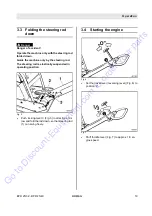
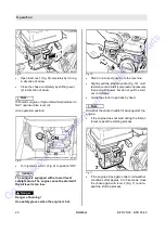
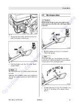
Page 19: ...steering rod is elastically suspended in operating position Fig 5 Push locking lever 3 Fig 5 in direction of ar row and fold the rod down so that steering rod 1 can swing freely 3 4 Starting the engine Fig 6 Set the travel lever reversing lever Fig 6 to position 0 Fig 7 Shift throttle lever Fig 7 to approx 1 3 en gine speed G o t o D i s c o u n t E q u i p m e n t c o m t o o r d e r y o u r p a ...

Page 20: ...urning Use safety gloves when the engine is hot Fig 10 Stand in a correct position to the machine Slightly pull the starter handle Fig 10 until resistance can be felt compression pressure then pull with power but do not pull the cord out completely Guide the starter rope back by hand L Note Do not let the starter handle hit back against the engine If the engine does not start during the first at t...

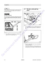
Page 21: ...throttle com mands 3 5 Work operation Caution Operate the vibratory plate only with full en gine speed as otherwise the centrifugal clutch may burn Fig 14 Shift the throttle lever Fig 14 to position MAX full speed L Note For short breaks you should always return the throttle lever to idle speed position this avoids pre mature wear of the centrifugal clutch Fig 15 Actuate travel lever 1 Fig 15 to f...

Page 22: ...g rod Fig 16 The vibratory plate compacts in forward and reverse or on the spot Fig 16 3 6 Vibratory plate getting stuck Fig 17 Lock steering rod 1 Fig 17 with locking lever 3 in the first locking position of notched rail 2 Fig 18 Keep moving throttle lever 1 Fig 18 between 3 4 and full throttle At the same time pull the vibratory plate by the steering rod to left and right until it comes free G o...

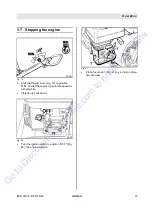
Page 23: ...ion MIN and let the engine run with idle speed for a short while Vibration is shut down Fig 20 Turn the ignition switch to position OFF Fig 20 the engine will stop Fig 21 Close fuel cock 1 Fig 21 by turning in direc tion of arrow G o t o D i s c o u n t E q u i p m e n t c o m t o o r d e r y o u r p a r t s ...

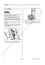
Page 24: ...e cross strut on the engine protection bow The machine must not swing about when be ing lifted Do not step or stand under loads being lifted Use only safe lifting gear of sufficient load bearing capacity Fig 22 Adjust steering rod 1 Fig 22 upright and en gage locking lever 3 in the notched rail Fig 23 Always attach the lifting gear rope to the en gine protection bow to load the vibratory plate on ...

Page 25: ... 20 25 BPR 25 32 BPR 25 40 4 Maintenance G o t o D i s c o u n t E q u i p m e n t c o m t o o r d e r y o u r p a r t s ...

Page 26: ...parate waste contain er and dispose of environmentally Before drawing out fuel the drum should rest for a longer period of time Under no conditions must the drum be rolled to the filling location just before drawing out fuel Choose the storage location for fuel so that spilled fuel will not cause any damage Do not stir up the sludge at the bottom of the drum with the suction hose Do not draw out f...

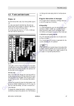
Page 27: ...40 down to 15 C may im pair the cold start ability but does not lead to en gine damage Temperature related lubrication oil changes ca be avoided by using multi purpose oils The following oil change intervals apply also for multi purpose oils Regular lubrication oil changes The longest time a lubrication oil filling should re main in the engine is 6 months Oil quality You should preferably use oils...

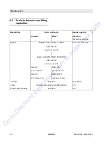
Page 28: ...E or CD SF 0 6 l to oil level mark SAE 10W 40 20 C to 30 C Engine oil SHPD CCMC D2 D3 PD1 SAE 15W 40 10 C to 40 C SAE 30 SAE 10 W 5 C to 30 C 5 C to 30 C SAE 40 SAE 20W 20 25 C to 40 C 10 C to 10 C Air filter Engine oil as required Fuel Gasoline unleaded or standard grade 3 7 l Vibrator shaft housing Engine oil 0 4 l G o t o D i s c o u n t E q u i p m e n t c o m t o o r d e r y o u r p a r t s ...

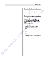
Page 29: ...the oil con sumption will drop to its normal level after a running time of approx 100 to 200 operating hours After 25 operating hours Change the engine oil Check engine and machine for leaks Check the valve clearance adjust if neces sary Retighten the fastening screws for air filter ex haust silencer fuel tank and other attach ments Tighten the screw connections on the ma chine Check the vibration...

Page 30: ...g air intake 4 11 Check the oil level in the vibrator shaft housing to bottom edge of filler opening Maintenance every 6 months 4 12 Change the engine oil 4 13 Check clean the spark plug 4 14 Clean the fuel sludge filter 4 15 Check tension change the V belt Dim mm inch 4 16 Clean change the air filter 4 17 Check adjust the valve clearance 4 18 Clean the fuel screen 4 19 Change the oil in the vibra...

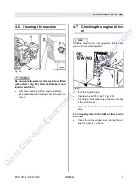
Page 31: ...4 7 Checking the engine oil lev el L Note Park the machine on level ground so that the en gine is in horizontal position Fig 26 Shut the engine down Unscrew the oil filler cap 1 Fig 26 The oil level must reach up to the bottom edge of the oil filler neck If the oil is below this level top up oil immedi ately For oil quality refer to the table of fuels and lu bricants Check the oil level again afte...

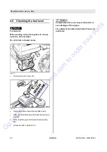
Page 32: ...1 Fig 27 Fig 28 Clean the area around the fuel filler neck Open the fuel filler cap and check the fuel level visually Fill in fuel through a funnel with screen Fig 28 Screw the filler cap back on Caution Contaminated fuel can cause malfunction or even damage of the engine For quality of fuel refer to the table of fuels and lubricants G o t o D i s c o u n t E q u i p m e n t c o m t o o r d e r y ...

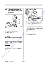
Page 33: ...ncorrectly handled inserts may be ineffective because of damage e g cracks and cause damage to the engine Danger Eye injury Wear your protective outfit safety goggles gloves Fig 30 Blow the paper insert 3 Fig 30 carefully out from inside to outside with dry clean com pressed air Clean the foam insert 2 in warm soapy water rinse it and let it dry thoroughly Soak the foam insert with clean engine oi...

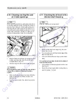
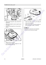
Page 34: ...t Caution Do not guide the water jet directly into air filter carburettor starter air intake and ignition switch After a sufficient soaking time clean off with a water or steam jet and blow out with com pressed air Run the engine warm for a while to avoid cor rosion 4 11 Checking the oil level in the vibrator shaft housing L Note Park the machine on level ground Fig 32 Unscrew filler and level plu...

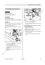
Page 35: ...ering handle Support the machine safely Unscrew the oil filler cap 1 Fig 33 Unscrew oil drain plug 2 and catch running out old oil Clean the drain plug and turn it in with a new seal ring 3 Fig 34 Adjust the engine horizontally Fill in new engine oil through the filler opening Fig 34 For quality and quantity of oil refer to the table of fuels and lubricants Screw the oil filler plug in Check the o...

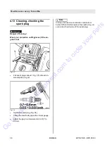
Page 36: ...socket 1 Fig 35 off and un screw spark plug 2 Fig 36 Clean the spark plug Fig 36 Check the electrode gap with a feeler gauge Adjust the gap to a measurement of 0 7 to 0 8 mm L Note In case of excessive combustion residuals or burned off electrodes replace the spark plug en sure correct heat value of the spark plug G o t o D i s c o u n t E q u i p m e n t c o m t o o r d e r y o u r p a r t s ...

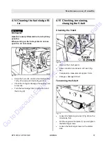
Page 37: ...y use a new one Turn the fuel sludge filter in tightly and mind the O ring 2 4 15 Checking tensioning changing the V belt Checking the V belt Fig 38 Remove the V belt guard Check condition and tension of V belt Fig 38 Compression measurement approx 5 mm Change a damaged V belt Tensioning the V belt Fig 39 Loosen the fastening screws 2 Fig 39 on the V belt side first Pull the engine carrier plate 1...

Page 38: ...ening screws 1 Fig 40 on the V belt side Press engine carrier plate 2 down Unscrew fastening screws 1 through the bores Unscrew socket head cap screws 4 Remove covering plate 3 Replace the V belt Attach the covering plate Turn socket head cap screws 4 in Turn fastening screws 1 in Tighten the V belt Install the V belt guard G o t o D i s c o u n t E q u i p m e n t c o m t o o r d e r y o u r p a ...

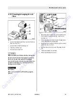
Page 39: ...rectly handled inserts may be ineffective because of damage e g cracks and cause damage to the engine Danger Eye injury Wear your protective outfit safety goggles gloves Fig 42 Blow the paper insert 3 Fig 42 carefully out from inside to outside with dry clean com pressed air Clean the foam insert 2 in warm soapy water rinse it and let it dry thoroughly Soak the foam insert with clean engine oil an...

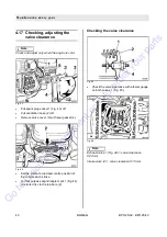
Page 40: ...asket 4 Fig 44 Set the piston to top dead centre position of the compression stroke For this purpose align triangle mark 1 Fig 44 on starter disc to the top bore 2 Checking the valve clearance Fig 45 Check the valve clearance with a feeler gauge on both valves 1 Fig 45 Fig 46 L Note Exhaust valve 1 Fig 46 valve clearance 0 20 mm Intake valve 2 valve clearance 0 15 mm G o t o D i s c o u n t E q u ...

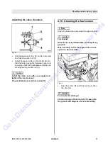
Page 41: ...sket and tighten the screws evenly Plug ventilation hose 2 into socket 5 4 18 Cleaning the fuel screen L Note Clean the fuel screen only when the engine is cold Caution Fire hazard Gasoline is easily inflammable do not spill any gasoline When working on the fuel system do not use open fire do not smoke Fig 48 Open fuel cock 1 Fig 48 by turning in direc tion of arrow Caution Environmental damage Ca...

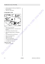
Page 42: ...in Fig 50 Disassemble the fuel tank For this purpose unscrew hexagon nut 1 Fig 50 and hexagon screw 2 Fig 51 Open hose clamp 1 Fig 51 pull the hose off Unscrew fuel screen 2 Clean the fuel screen check the condition of the screen holes replace if necessary L Note Check seal 3 replace the seal if damaged Turn the fuel screen with seal in tightly G o t o D i s c o u n t E q u i p m e n t c o m t o o...

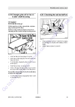
Page 43: ...t old oil Turn the drain plug tightly back in with a new seal ring 4 Park the machine on level ground Fill in oil through the filling and oil level control bore up to the bottom edge of the filling bore For quality and quantity of oil refer to the table of fuels and lubricants Turn the filler and level plug tightly back in with a new seal ring 1 4 20 Checking the rubber buffers Fig 53 Check all ru...

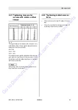
Page 44: ...sult in a 90 utilization of the screw s yield point at a coefficient of friction µ total 0 14 Compliance with the tightening torque is checked with torque wrenches L Note Self locking nuts must always be replaced once they have been unscrewed 4 22 Tightening bolted connec tions Check all screws for tight fit tighten if neces sary Check the machine for damage and leaks if necessary have faults corr...

Page 45: ...the cylinder head cover off spray the rocker chamber with a mixture of diesel fuel and 10 anti corrosion oil Then fasten the cover again Crank the engine several times to spray the combustion chamber throttle lever in stop po sition Take the V belt off and spray the grooves of the V belt pulleys with anti corrosion oil Re move the anti corrosion oil before taking the machine back into service Clos...

Page 46: ... 20 47 BPR 25 32 BPR 25 40 5 Trouble shooting G o t o D i s c o u n t E q u i p m e n t c o m t o o r d e r y o u r p a r t s ...

Page 47: ...ver a fault occurs you should there fore thoroughly read these instruction on correct operation and maintenance If you cannot locate the cause of a fault or rectify it yourself by following the trouble shooting chart you should contact the service departments at our branch offices or deal ers On the following pages you will find a selection of fault remedies It goes without saying that not all pos...

Page 48: ...ault corrected Air filter clogged Clean or replace the filter cartridge Engine defective Change the engine have the fault rectified Carburettor defective Replace the carburettor No vibration Centrifugal clutch defective Replace the centrifugal clutch V belt broken Replace the V belt Engine com pression Valve clearance Check and adjust the valve clearance Engine over heating Insufficient cooling ai...

Page 49: ...ne needs We sell worldwide for the brands Genie Terex JLG MultiQuip Mikasa Essick Whiteman Mayco Toro Stone Diamond Products Generac Magnum Airman Haulotte Barreto Power Blanket Nifty Lift Atlas Copco Chicago Pneumatic Allmand Miller Curber Skyjack Lull Skytrak Tsurumi Husquvarna Target Stow Wacker Sakai Mi T M Sullair Basic Dynapac MBW Weber Bartell Bennar Newman Haulotte Ditch Runner Menegotti M...

Reviews: