background image


Assembly

Assembly

Assembly

Assembly    

    WARNING:

WARNING:

WARNING:

WARNING:    


When assembling or inserting the
be connected to the mains. 


Failure to use the mounting fixtures may lead to a 


    CAUTION

CAUTION

CAUTION

CAUTION::::    


Before mounting, check that the wall 


When drilling the holes in the wall always make sure that no existing electrical cables or other objects are 
damaged.  


Make sure that the vents are clear of obstacles and are not covered.


    NOTE

NOTE

NOTE

NOTE::::    Recomm

Recomm

Recomm

Recommendations for preparation work

endations for preparation work

endations for preparation work

endations for preparation work


When installing, ask another person


Wear protective gloves to prevent injuries from any sharp edges.


1111    

2222    


Mounting at the wall   


The hood is mounted at the wall or 
centrally above the hob in conformance


Remove the grease filter grid or aluminum grease filter (depending on the model).


Select the fume outlet and set the lever to the appropriate position, see “Selecting the fume outlet”.


Mounting at the wall

Mounting at the wall

Mounting at the wall

Mounting at the wall    


Mark the necessary holes for the wall mounting by using the supplied drill template and check them with a 
spirit level. 


Drill  two  mounting  holes  Ø  8  mm  into  the  wall  and  insert  the  dowel  pins  (1).  Then  rotate  the  mounting 
screws (2) as far as these stick out about 4 mm from the wall.


Suspend the hood and tighten the screws through the hood body. Check the secure fitting and 
position. 


Mounting below the wall u

Mounting below the wall u

Mounting below the wall u

Mounting below the wall unit

nit

nit

nit    


Hold the hood to the specified cabinet position and draw the drilling points from the inside of the unit corr
sponding to the four screw holes. Check them with a spirit level.

19 

the extraction filter as well as the carbon filter mat

Failure to use the mounting fixtures may lead to a risk of electric shock

risk of electric shock

risk of electric shock

risk of electric shock. 

check that the wall or wall unit has sufficient load capacity to bear

When drilling the holes in the wall always make sure that no existing electrical cables or other objects are 

Make sure that the vents are clear of obstacles and are not covered. 

endations for preparation work

endations for preparation work

endations for preparation work

endations for preparation work    

person to assist. 

Wear protective gloves to prevent injuries from any sharp edges. 

3333    

4444    

5555    


     Mounting below the wall unit 


at the wall or below a suitable wall unit. Determine the position

conformance with the specified safety distances. 

Remove the grease filter grid or aluminum grease filter (depending on the model). 

the lever to the appropriate position, see “Selecting the fume outlet”.

necessary holes for the wall mounting by using the supplied drill template and check them with a 

mounting  holes  Ø  8  mm  into  the  wall  and  insert  the  dowel  pins  (1).  Then  rotate  the  mounting 

screws (2) as far as these stick out about 4 mm from the wall. 
Suspend the hood and tighten the screws through the hood body. Check the secure fitting and 

to the specified cabinet position and draw the drilling points from the inside of the unit corr

sponding to the four screw holes. Check them with a spirit level. 

mat, the appliance must not 

bear the extractor hood. 

When drilling the holes in the wall always make sure that no existing electrical cables or other objects are 

6666    


position of the extractor hood 


the lever to the appropriate position, see “Selecting the fume outlet”. 

necessary holes for the wall mounting by using the supplied drill template and check them with a 

mounting  holes  Ø  8  mm  into  the  wall  and  insert  the  dowel  pins  (1).  Then  rotate  the  mounting 

Suspend the hood and tighten the screws through the hood body. Check the secure fitting and horizontally 

to the specified cabinet position and draw the drilling points from the inside of the unit corre-

Summary of Contents for DU 622.1

Page 1: ...1 1 1 1 DU DU DU DU 623 1 623 1 623 1 623 1 IX IX IX IX H H H HOUSEHOLD OUSEHOLD OUSEHOLD OUSEHOLD B B B BUILT UILT UILT UILT IN IN IN IN C C C COOKER OOKER OOKER OOKER H H H HOOD OOD OOD OOD Bedienungsanleitung Garantie Bedienungsanleitung Garantie Bedienungsanleitung Garantie Bedienungsanleitung Garantie Instruction Manual Instruction Manual Instruction Manual Instruction Manual ...

Page 2: ...10 Reparaturen Seite 11 Störungsbehebung Seite 11 Technische Daten Seite 12 Garantie Seite 13 Entsorgung Seite 14 ENGLI ENGLI ENGLI ENGLISH SH SH SH Contents Contents Contents Contents Introduction Page 15 General Notes Page 15 Special safety Information for this Unit Page 16 Unpacking the Appliance Page 17 Overview of the Appliance Page 17 Installation Page 18 Startup Operation Page 21 Cleaning a...

Page 3: ...che Verletzungsrisiken auf Weist auf mögliche Gefährdungen für das Gerät oder andere Gegenstände hin Hebt Tipps und Informationen für Sie hervor Allgemeine Hinweise Allgemeine Hinweise Allgemeine Hinweise Allgemeine Hinweise Lesen Sie vor Inbetriebnahme dieses Gerätes die Bedienungsanleitung sehr sorgfältig durch und bewahren Kassenbon gut auf Falls Sie das Gerät an Dritte weitergeben geben Sie au...

Page 4: ...sthaube in Betrieb ist Das Gerät NIE ohne befestigte Aluminium Dunstfilter benutzen Bei gleichzeitigem Betrieb der Dunstabzugshaube im Abluftbetrieb und Feuerstät ten darf im Aufstellraum der Feuerstätte der Unterdruck nicht größer sein als 4 Pa 4x10 5 bar Bei der Ableitung der Abluft sind die Vorschriften der zuständigen örtlichen Be hörden einzuhalten Befolgen Sie die Montageanweisung Beachten S...

Page 5: ...er oder dem Kundendienst durch ein gleichwertiges Kabel ersetzen lassen Wenn Kabel oder Stecker beschädigt sind dürfen Sie das Gerät nicht mehr benutzen Auspacken des Gerätes Auspacken des Gerätes Auspacken des Gerätes Auspacken des Gerätes Nehmen Sie das Gerät aus seiner Verpackung Verpackungsmaterial wie Folien Füllmaterial Kabelhalter und Kartonverp Überprüfen Sie das Gerät auf eventuelle Trans...

Page 6: ...m b 75 cm betragen Bei Gasgeräten muss der Abstand mindestens 65 cm b 75 cm betragen Bei Gasgeräten muss der Abstand mindestens 65 cm b 75 cm betragen Bei Gasgeräten muss der Abstand mindestens 65 cm b Wenn die Installationsanweisungen für die Gaskochgeräte einen größeren Abstand vorschreiben ist wie nachstehend beschrieben in zwei Möglichkeiten betreiben B Umluft den Hebel der sich an der Motor G...

Page 7: ...unstfilter sowie der Kohlefiltermatte mit dem Netzstrom verbunden sein Die Nichtbeachtung der Befestigungsvorrichtung kann zur Stromschlaggefahr Stromschlaggefahr Stromschlaggefahr Stromschlaggefahr führen Prüfen Sie vor der Montage die Wand bzw den Oberschrank auf Tragfähigkeit der Abzugshaube Bohrlöcher in der Wand stets darauf keine bereits vorhandenen elektr schen Leitungen oder andere verdeck...

Page 8: ...berschrank und drehen Sie die Muttern 4 durch den Haubenkörper fest Für den Abluftbetrieb setzen Sie den Anschlussstutzen mit Rückschlagklappen 5 von oben auf den Luft austritt ein Hieran ist ein flexibler Abluftschlauch nicht im Lieferumfang enthalten mit Ø 120 mm Innen durchmesser zu befestigen und mit der Abzugsöffnung nach außen zu verbinden Für den Umluftbetrieb schließen Sie den Luftaustritt...

Page 9: ...ag elektrischen Schlag führen Gerätenetzanschlussstecker nicht Lassen Sie die Netzsteckdose durch einen Fac mann ersetzen wenn diese für den Gerätenetzstecker nicht geeignet ist Die Zugänglichkeit des Netzsteckers muss gewährleistet sein um das Gerät im Notfall sofort von der Sie ob die Netzspannung die Sie benutzen wollen mit der des Gerätes übereinstimmt Die Ang ben hierzu finden Sie auf dem Typ...

Page 10: ...s das Gerät vollständig abgekühlt ist Das Gerät nie mit Dampfreinigungsgeräten reinigen Feuchtigkeit könnte in elektrische Bauteile gelangen Heißer Dampf kann zu Schäden an Kunststoffteilen führen Das Gerät muss trocken sein bevor Sie es wieder in Betrieb nehmen Benutzen Sie keine Drahtbürste oder andere scheuernde Gegenstände scharfen oder scheuernden Reinigungsmittel Verwenden Sie für die Reinig...

Page 11: ...ennungsgefahr Es besteht Verbrennungsgefahr Verwenden Sie das richtige Leuchtmittel 1 1 1 1 x 28 W Typ E14 x 28 W Typ E14 x 28 W Typ E14 x 28 W Typ E14 Entnehmen Sie das Dunstfiltergitter bzw die Aluminium Dunstfilter Modellabhängig Drehen Sie die defekte Glühlampe aus dem Gewinde und drehen Sie das neue Leuchtmittel ein filtergitter bzw die Aluminium Dunstfilter wieder ein Reparaturen Reparaturen...

Page 12: ...ebung Behebung ür den Umluftbetrieb benötigte matte richtig eingesetzt Ist der für den Abluftbetrieb benötigte Luft Überprüfen Sie die Kohlefilter Aktivkohlefiltermatte Überprüfen Sie den Luftauslass Das Leuchtmittel ist defekt wurde falsch nicht fest in der Fassung Überprüfen Sie das Leuchtmittel siehe Leuchtmittel auswechseln Die Dunstfilter sind verschmutzt Reinigen Sie die Dunst Falls Sie nach...

Page 13: ...Garantie Garantie Garantie Garantiebedingungen Garantiebedingungen Garantiebedingungen Garantiebedingungen 1 Gegenüber Verbrauchern gewähren wir bei privater Nutzung des Geräts eine Garantie von 24 Monaten ab Kaufdatum Ist das Gerät zur gewerblichen Nutzung geeignet gewähren wir beim Kauf durch Unternehmer für das Gerät eine Garantie von 12 Monaten Die Garantiezeit für Verbraucher reduziert sich a...

Page 14: ...te Nacherfüllung Rücktritt Schadensersatz und Minderung h diese Garantie nicht berührt Sollte Ihr Gerät innerhalb der Garantiezeit einen Mangel aufweisen bitten wir Sie die Internetseite des Se www sli24 de aufzurufen Nach Eingabe des Gerätetyps wird Ihnen angezeigt wie die Reklamation bearb C Bomann GmbH C Bomann GmbH C Bomann GmbH C Bomann GmbH Heinrich Horten Straße 17 D 47906 Kempen Entsorgung...

Page 15: ...n for your safety is specially marked It is essential to comply with these instructions in order to avoid accidents and prevent damage to the machine o your health and indicates possible injury risks o the machine or other objects This highlights tips and information General Notes General Notes General Notes General Notes instructions carefully before putting the appliance into operation and keep ...

Page 16: ...es which are powered b other forms of energy as electricity served together the pressure in the room should not exceed 4 Pa 4x10 5 bar Regulations concerning the discharge of air have to be fulfilled Follow the installation instructions Note the instructions that we give you in the chapter Installation This appliance can be used by children children children children aged from 8 years and above an...

Page 17: ...rson and with Unpacking the Appliance Unpacking the Appliance Unpacking the Appliance Unpacking the Appliance Remove the appliance from its packaging packaging material such as foils filler cable holder and cardboard packaging To prevent hazards check the appliance for any transport damage In case of damage do not put the appliance into operation Contact your distributor sidue or dust may have col...

Page 18: ...tallation instructions for the gas cooker specify a greater distance this distance must be taken into consi as described below in two modes B Recirculation mode that is located on the motor fan unit is to set in the corresponding posi for the extraction mode and the cover for the recirculation mode tructions that we give you in Assembly as well The extracted air may not be vented into a flue which...

Page 19: ... fixtures may lead to a risk of electric shock risk of electric shock risk of electric shock risk of electric shock check that the wall or wall unit has sufficient load capacity to bear When drilling the holes in the wall always make sure that no existing electrical cables or other objects are Make sure that the vents are clear of obstacles and are not covered endations for preparation work endati...

Page 20: ...or extraction mode insert the connecting piece with non return valves 5 from above onto the air outlet Thereto a flexible extraction hose not supplied with an inner diameter of Ø 120 mm must be fitted and connected to the outside by an extraction vent For recirculation mode close the air outlet by putting on the cover 6 Reinstall the grease filter grid or aluminum grease filter mat mat mat mat for...

Page 21: ...n Startup Operation Startup Operation extractor hood is operated via two slide switches The lighting as well as the fan settings must be switched on and off with the corresponding switches 1 Lowest fan setting 2 Moderate fan setting 3 Highest fan setting 1 Lighting on low speed This setting is suitable for cooking on a low flame to circulate the air around the kitchen motor runs at moderate speed ...

Page 22: ...ty bulb and screw in new bulb Reinstall the grease filter grid or aluminum grease filter 22 housing use a mild detergent and a soft cloth to prevent scratching The appliance can be used again after everything has dried properly tractor hood in recirculation mode you must replace the activated bon filter depending on the model depending on the model depending on the model depending on the model Gre...

Page 23: ...re you contact an authorized specialist Before you contact an authorized specialist Before you contact an authorized specialist Before you contact an authorized specialist The following problems can be solved by you by checking for the possible cause Solution Solution Solution Solution Is the unit not connected to mains power Have you set the power level Insert the plug properly in the contact soc...

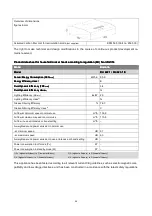
Page 24: ...ass1 1 1 1 E Fluid Dynamic Efficiency FDE Fluid Dynamic Efficiency FDE Fluid Dynamic Efficiency FDE Fluid Dynamic Efficiency FDEhood hood hood hood 3 4 Fluid Dynamic Efficiency class Fluid Dynamic Efficiency class Fluid Dynamic Efficiency class Fluid Dynamic Efficiency class2 2 2 2 G Lighting Efficiency LEhood lux W 2 0 Lighting Efficiency class3 G Grease Filtering Efficiency 76 3 Grease Filtering...

Page 25: ...al equipment in the domestic waste equipment that you will no longer use to the collection points provided for their This helps avoid the potential effects of incorrect disposal on the environment and human health This will contribute to the recycling and other forms of reutilization of electrical and electronic equipment Information concerning where the equipment can be disposed of can be obtaine...

Page 26: ...26 ...

Page 27: ...27 ...

Page 28: ...28 C C C C B B B Bo o o om m m ma a a an n n nn n n n G G G Gm m m mb b b bH H H H w w w ww w w ww w w w b b b bo o o om m m ma a a an n n nn n n n d d d de e e e Made in P R C Stand 12 16 ...

Reviews: