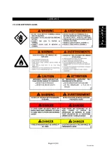
Page 28 / 43
INSTALLATION AND CIRCUIT
–
CONNECTING OPTIONS
V -2-7-Wiring options:
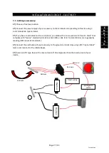
A bilge pump is fitted as standard to the boat. However, it is also possible to add extra accessories
under certain conditions:
The accessories you want to add must be connected to the console.
Accessories are divided into two categories:
A
→
accessories that are used or which may be used continuously during normal use of
the boat,
B
→
accessories that are used intermittently
A
an
d
B
Bilge fan
Cigar lighter (standard)
Radio
Miscellaneous lighting
Depth sounder
Audio warning
GPS
Miscellaneous electronic
equipment
Searchlight
Shower pump
Alarm system
Max. power
60W max.
Refrigerator
VHF
180W max.
WARNING
You must make sure that the total power of the accessories you add
in column A is 180W (15A) or less AND that the max power of an
accessory in column B is 60W (5A) or less.
The sections of the different cables in the wiring circuit were
calculated using these figures; not following this rule may lead to
electrical faults and cause short circuits.
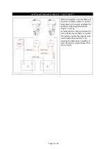
You may connect the options directly to the positive and negative console ground terminal (within
the max. power limits), using an approved fuse-holder.
NOTE:
If you are getting several pieces of electrical equipment installed, the total immediate
consumption could potentially exceed your outboard engine’s charge capacity.
For example, the electrical wiring harness can accept instant consumption of 285W (including
navigation lights and bilge pump), which is a little less than a 24A output current. The alternators in
the engines fitted generally provide 15 A when at full throttle. Check your engine’s technical
documentation. You should therefore avoid using this equipment over a long period of time, as you
run the risk of flattening the battery and not being able to restart the engine.
Summary of Contents for Sunrider 700
Page 2: ......
Page 44: ...Page 42 43 VI 2 4 Roll Bar SIGNALETIQUE VII 1 POSITION DES AUTOCOLLANTS...
Page 45: ...Page 43 43 Edition 1 F R A N C A I S SIGNALETIQUE VII 2 DESCRIPTIF DES AUTOCOLLANTS...
Page 46: ...TM ERRATUM EXP 700 SUNRIDER 700 MOTORISATION ESSENCE...
Page 49: ...ERRATUM EXP 700 SUNRIDER 700 F R E N TM 46 Avenue Gustave Eiffel 33600 PESSAC...
Page 51: ......
Page 93: ...Page 42 43 VI 2 4 Roll Bar LABELLING VI 1 POSITION OF STICKERS...
Page 94: ...Page 43 43 First edition E N G L I S H LABELLING VII 2 DESCRIPTION OF LABELS...
Page 95: ...TM ERRATUM EXPLORER 700 SUNRIDER 700 FUEL AND POWER CIRCUIT...
Page 100: ......
Page 113: ...P gina 13 44 Edici n 1 E S P A O L...
Page 144: ...P gina 44 44 SE ALIZACI N VII 2 DESCRIPCI N DE AUTOADHESIVOS...
Page 145: ...TM ERRATUM EXPLORER 700 SUNRIDER 700 CIRCUITO DE COMBUSTIBLE Y MOTOR...
Page 150: ......
Page 192: ...Pagina 42 43 VI 2 4 Roll bar SEGNALETICA VII 1 POSIZIONE DEGLI AUTOADESIVI...
Page 193: ...Pagina 43 43 Edizione 1 I T A L I A N O SEGNALETICA VII 2 DESCRIZIONE DEGLI AUTOADESIVI...
Page 194: ...TM ERRATA CORRIGE EXPLORER 700 E SUNRIDER 700 CIRCUITO CARBURANTE E MOTORIZZAZIONE...
Page 199: ......
Page 241: ...Seite 42 43 VI 2 4 Ger tetr ger WARNSCHILDER VII 1 ANORDNUNG DER SICHERHEITSAUFKLEBER...
Page 242: ...Seite 43 43 Ausgabe 1 D E U T S C H WARNSCHILDER VII 2 BESCHREIBUNG DER SICHERHEITSAUFKLEBER...
Page 243: ...TM ERRATUM EXPLORER 700 SUNRIDER 700 CIRCUIT KRAFTSTOFF UND MOTORSYSTEM...
Page 247: ...TM TRYKKFEIL EXPLORER 700 SUNRIDER DRIVSTOFFKRETSL P OG MOTOR...


