background image

For Training Purposes Only

Sept 04

2-21

P I L O T T R A I N I N G G U I D E

AUTOMATIC FLIGHT CONTROL SYSTEM

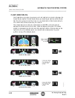
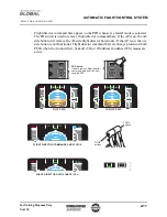
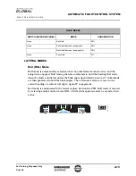
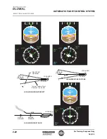
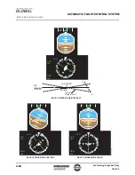
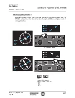
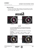
Localizer (LOC) Mode

Localizer mode provides for automatic intercept, capture and tracking of the front 
course localizer beam, to line up on the centerline of the runway in use.

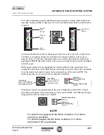
Localizer capture and tracking commands are based on the distance-to-transmitter. 
The FMS will output distance to tuned navaid or distance to destination, based on the 
following conditions:

If the FMS is used to autotune the LOC, the FMS will output the distance to the 
tuned LOC transmitter

If the FMS is tuned manually by LOC-ident on the CDU, the FMS will output the 
distance to the tuned LOC transmitter, regardless of approach or flightplan

If the LOC frequency is manually tuned with a LOC-frequency on the CDU, or if 
tuned on the RMU, and the FMS will output distance to destination selected in the 
flight plan

If the LOC frequency is manually tuned with a LOC-frequency on the CDU, or if 
tuned on the RMU, and the FMS does not have a destination selected, no distance 
information will be output by the FMS. In this case, the AFCS will use estimated 
distance

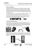
The AFCS priority for determining distance to LOC transmitter is:

Distance-to-station (DME) information, if the DME is valid and co-located with 
the localizer transmitter

If DME information is not available, or not co-located, the distance to localizer is 
based on radio altitude, true airspeed, glideslope deviation and an assumed flight 
path angle of 3°

If, in addition to invalid DME, the radio altitude is invalid, the AFCS will use FMS 
distance information

If the FMS is also unavailable, then AFCS will use a default value of 10 nm

If a destination other than the one designated in the FMS flight plan is used and the 
LOC-frequency is manually tuned with a LOC-frequency on the CDU, or tuned on the 
RMU, and DME and RAD ALT are not available, the FMS will output erroneous 
distance to destination data. To prevent potential problems in this circumstance, a limit 
was placed on the value the AFCS will accept from the FMS for distance (30 nm). 
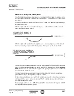
Testing showed that when performing a close-in capture (7 - 10 nm) using the 
maximum value for distance (30 nm), the LOC overshoots on initial capture were 
within acceptable limits and were damped out within 2 oscillations.

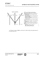
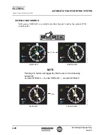
FD roll commands are ± 30° when capturing localizer. During localizer track mode, 
the roll commands are ± 24°. Roll rate commands are 7°/sec. during capture and 5.5°/
sec. during track modes. The optimum intercept angle is 45°. If intercept angle is 
greater than 45°, course cut limiting may occur. As LOC moves from ARMED to 
ACTIVE, the LOC will flash for approximately 5 seconds, when active.

Summary of Contents for Primus 2000XP

Page 1: ...ngagement 2 6 Autopilot Disengagement 2 7 Yaw Damper 2 8 PFD Annunciation 2 9 Flight Director FD 2 10 Guidance Panel 2 12 Flight Director Modes 2 14 Lateral Modes 2 15 Bearing BRG Source 2 27 VOR LOC...

Page 2: ...P I L O T T R A I N I N G G U I D E AUTOMATIC FLIGHT CONTROL SYSTEM 2 ii For Training Purposes Only Sept 04 PAGE INTENTIONALLY LEFT BLANK...

Page 3: ...ght Instrument System EFIS the Air Data Computers ADC the Inertial Reference System IRS the Flight Management System FMS the Fault Warning Computer FWC and the Data Acquisition Unit DAU DESCRIPTION Al...

Page 4: ...ommand bar output for display If an autopilot or flight director mode is armed or active the annunciator on the appropriate button is illuminated SPD MAN FMS CRS 1 CRS 2 PUSH DCT PUSH DCT ALT HDG DN U...

Page 5: ...APR VS BC PUSH CHG PUSH SYNC MAX THRUST IDLE REV MAX REV ENG RUN OFF OFF R L RUDDER CONTROL SURFACE POSITION CH 1 CH 2 TRIM SYSTEM IAC 1 IAC 2 FGC 2 DUAL ELEVATOR SERVO DUAL AILERON SERVO YAW DAMPER...

Page 6: ...el provides control functions while the low priority channel operates in a back up mode The autopilot yaw damper actuators and pitch trim interface can only be driven by the priority channel In the ev...

Page 7: ...ion is selected via the source identifier received from selected PFD symbol generator The data received includes IRS Roll angle Normal acceleration Pitch angle Ground speed Roll rate True track angle...

Page 8: ...throughout the range Pitch 50 Roll 75 Once engaged the autopilot will reduce the pitch and roll angles below control limits Autopilot control limits Roll 35 except in Approach APP mode When in APP mod...

Page 9: ...isengaged and the flight director is resynchronized Releasing the TCS button reengages the servo clutches and autopilot is engaged if within normal pitch and roll limits Where applicable the flight di...

Page 10: ...autopilot the yaw damper operates in an active standby configuration When engaged the active yaw damper will center both linear actuators The YD will not automatically engage once the airplane is airb...

Page 11: ...30000 GX_02_008 AP1 TCS TCS DN UP P I T C H VNAV VS Pitch Wheel AP ENGAGE STATUS TOUCH CONTROL STEERING TCS STATUS VERTICAL SPEED REFERENCE VS Target Readout VS Pointer 1000 VS 1000 0 1 2 3 1 VS Targ...

Page 12: ...vertical modes on the right side above the attitude sphere Low bank mode is annunciated via green eyebrow on top of the attitude sphere 300 LIM LNAV VPTH AP1 SPD VOR VPTH 23500 ATT2 ADC1 20 20 20 0 8...

Page 13: ...th PFDs when Go Around GA Takeoff TO or Windshear Guidance WS modes are active 20 20 10 10 10 10 20 20 20 FD Switch Used to remove flight director command bars from the non coupled PFD GX_02_010 20 20...

Page 14: ...heading Bank BANK Switch Used to manually select bank angle limit in HDG or VOR modes Heading HDG Button Push Synchronize PUSH SYNC Button Used to move the heading bug on PFD When pushed causes headi...

Page 15: ...button removes both FD offside button removes offside FD AP ON AP OFF Autopilot AP Switch Used to engage and disengage autopilot When autopilot engaged the yaw damper is engaged simul taneously Diseng...

Page 16: ...NK High Low Bank HDG or VOR mode only Eyebrow on attitude sphere low bank only VERTICAL MODES SWITCH GUIDANCE PANEL MODE ANNUNCIATION VS Vertical Speed Hold VS None Automatic Altitude Capture ASEL ALT...

Page 17: ...6 commands are then generated to hold the bank angle The roll mode reference is reset to the current heading or current roll angle upon AP engagement Roll mode is annunciated in the lateral capture fi...

Page 18: ...ding through an altitude of 35 050 feet the FGC automatically transitions to the low bank limit of 17 If the roll angle is greater than 6 an automatic bank limit transition will not occur until the ro...

Page 19: ...gh frequency Omnidirectional Range VOR Localizer LOC FMS Lateral Navigation LNAV If in ROL mode when NAV is selected heading select mode is automatically activated A capture of any armed lateral navig...

Page 20: ...commands are 14 and roll rate commands 4 sec If selected VOR is retuned to another VOR frequency while in VOR capture track or overstation VOR mode cancels and rearms automatically When the airplane...

Page 21: ...TO FROM transition The period of time elapsed is calculated using true airspeed and altitude The higher the altitude the longer it takes to get through cone of confusion The higher the airspeed the fa...

Page 22: ...VNAV 0 856M VOR1 CRS 090 HDG 030 SRP VOR 1 ATT2 ADC1 20 20 10 10 10 10 20 20 20 N 3 3 3 0 W 2 4 2 1 S 1 5 12 E 6 3 21 1NM VOR MODE CAPTURE VOR MODE INTERCEPT SELECTED COURSE SELECTED HEADING Typical C...

Page 23: ...formation if the DME is valid and co located with the localizer transmitter If DME information is not available or not co located the distance to localizer is based on radio altitude true airspeed gli...

Page 24: ...HDG 040 SRP ATT2 ADC1 20 20 10 10 10 10 20 20 20 N 3 3 30 W 2 4 21 S 1 5 12 E 6 3 10 0NM LIM LOC VS AP1 SPD VOR VNAV 0 856M LOC1 CRS 090 HDG 040 SRP ATT2 ADC1 20 20 10 10 10 10 20 20 20 N 3 3 3 0 W 2...

Page 25: ...back course localizer signal BC mode is identical to LOC mode except that the transmitter is located 2000 feet in front of the touch down point The course arrow must be set to the front course runway...

Page 26: ...1 S 1 5 1 2 E 6 3 10 LIM HDG ALT AP1 SPD BC VNAV 0 856M LOC1 CRS 090 HDG 330 ATT2 ADC1 20 20 10 10 10 10 20 20 20 N 33 30 W 24 2 1 S 15 1 2 E 6 3 GX_02_020 BACK COURSE MODE TRACK BACK COURSE MODE CAPT...

Page 27: ...navigation to a LOC or VOR approach via the APR or BC button The selected NAV source must be FMS NAV radio must be tuned to the approach frequency and preview mode selected to allow a NAV transfer to...

Page 28: ...I D E AUTOMATIC FLIGHT CONTROL SYSTEM 2 26 For Training Purposes Only Sept 04 Previewed Approach DTK 360 HDG 330 SRP N 33 3 0 W 2 4 2 1 S 1 5 1 2 E 6 3 23 4NM FMS1 LOC1 Preview Navigation Source Prev...

Page 29: ...control panel located on the glareshield MINIMUMS BARO Hpa RAD IN BARO SET NAV SRC BRG V L BRG FMS HSI Honeywell PUSH STD MINIMUMS BARO Hpa RAD IN BARO SET NAV SRC BRG V L BRG FMS HSI Honeywell PUSH...

Page 30: ...ggle the NAV source in the following sequence on side VOR LOC X side VOR LOC on side VOR LOC CRS 360 HDG 030 VOR 1 N 3 3 30 W 2 4 21 S 1 5 12 E 6 3 VOR1 CRS 360 HDG 030 VOR VOR 2 N 3 3 30 W 2 4 21 S 1...

Page 31: ...cancel V L as primary NAV source and will set on side FMS as primary NAV source Pushing FMS button will toggle the NAV source in the following sequence on side FMS X side FMS LTRK if installed on side...

Page 32: ...ude is above the airplane s present altitude and there is adequate thrust FLC mode will climb at the speed reference until preselected altitude is captured If thrust is inadequate FLC mode will hold p...

Page 33: ...airspeed tape of the selected PFD The MAN speed bug is cyan and can be in either kts or MACH FMS speed selection is programmed in the active flight plan in the FMS A Mach speed bug will appear on the...

Page 34: ...e with altitude configuration and or airspeed changes while climbing descending or in level flight Vertical Speed VS Select Mode VS mode is used to maintain a pilot selected vertical speed reference F...

Page 35: ...within 2000 feet of current altitude and the altitude rate required to fly a constant 0 05g capture curve is less than the current airplane inertial climb rate ASEL will capture when descending towar...

Page 36: ...Vertical Navigation VNAV Modes VNAV mode contains 4 vertical submodes that can be flown using speed and altitude targets that are programmed in the active flight plan of the FMS A double C chord aura...

Page 37: ...pe signals which enables the pilot to fly a fully coupled ILS approach APR modes are based on vertical path deviation and valid glideslope on the selected PFD Review the Localizer section for further...

Page 38: ...lope arm or capture and dual couple status A valid CAT 2 status is indicated on the PFD A CAT 2 window also appears to display deviation from the beam The fully coupled dual arrow ILS approach becomes...

Page 39: ...TURE APPROACH MODE INTERCEPT INBOUND COURSE LOCALIZER TX SELECTED HEADING Typical Capture Point Between 1 and 2 Dot RUNWAY 090 045 APPROACH MODE TRACK OUTER MARKER 4 0 7 0 MILES MIDDLE MARKER 3500 FEE...

Page 40: ...les will provide full takeoff thrust until TO mode is cleared TO mode can be cleared by selecting the AP on PIT or by selecting another vertical mode GO AROUND GA MODE GA mode provides pitch and later...

Page 41: ...e can be activated by either depressing the throttle mounted TOGA button or advancing the thrust levers towards takeoff when a windshear warning has been displayed on EFIS WSHR mode will provide verti...

Page 42: ...matically disconnect the autopilot WSHR mode cannot be canceled when a Windshear Warning is present When the WSHR mode is activated the attitude at which the aircraft will reach stall speed is indicat...

Page 43: ...rget is not manually selectable through the speed knob on the guidance panel while EDM is active Changing the FMS MAN switch position of the speed knob on the guidance panel has no effect while EDM is...

Page 44: ...hrottles are manually disengaged and reengaged while in EDM The autothrottles are not automatically reengaged if disengaged Auto engagement occurs only upon initiation of the emergency descent mode Th...

Page 45: ...LIGHT DIRECTOR EICAS MESSAGES Cont GX_02_045 AFCS 1 2 FAIL Indicates that AFCS one or both functions has failed The AFCS functions include yaw damper autopilot and flight director YD NOT CENTERED Indi...

Page 46: ...CONT GX_02_046 CB AFCS SYSTEM 1 3 A T CTLR A T SERVOS AP 1 SERVOS AP 2 SERVOS GUID PANEL CH 1 GUID PANEL CH 2 AC 1 DC 1 DC1 DC 2 BATT DC ESS IN IN IN IN IN IN CCBP CB AFCS SYSTEM 2 3 IAC 1 IAC 2 IAC 3...

Reviews: