background image

1-866-771-2663  |  Page 7

ASSEMBLY INSTRUCTIONS

1.

 Flip the tank housing (D) upside down and 

attach the wheel assembly (J) to the base of the 
tank housing (D) using 2 M8 x 16 screws (CC).

2.

 Attach the anchoring arms (FF) onto the base of 

the tank housing (D) using 6 silver M6 x 12 screws 
(BB) and 6 M6 nuts (DD).

3.

 Attach the tank housing supporter (G) into the 

tank housing (D) using 1 M8 x 16 screw (CC) and 
2 M5 x 12 screws (AA). Do not fully tighten to 
allow room for adjustment later in the assembly 
process.

J

D

D

D

CC

G

AA

FF

BB

DD

CC

Summary of Contents for HYPH4601-12

Page 1: ...y other appliance Improper installation adjustment alteration service or maintenance can cause injury or property damage Read the owner s manual thoroughly before installing or servicing this result c...

Page 2: ...2 74kPa Use LP propane tanks with the following dimensions diameter 12in height 18in weight 20lbs You must use a propane tank that has a collar to protect the gas valve DO NOT fill tank over 80 perce...

Page 3: ...ction This heating appliance should not be used on plastic or artificial wood decks Inspect the gas hose and all connections to the propane tank prior to each use Always follow lighting instructions c...

Page 4: ...BESIDE OR UNDER THIS HEATER WHILE IN USE THEY WILL BE SUBJECT TO RADIANT HEAT AND COULD BE SERIOUSLY DAMAGED Combustible materials should not be within 24 inches of the top of the unit or within 36 i...

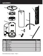
Page 5: ...GG Wrench 1 HARDWARE Before beginning assembly of this product be sure all parts are present Compare parts with package contents list and hardware contents list If any part appears to be missing or da...

Page 6: ...6 E F Item Description Qty A Upper Reflector 1 B Glass Tube Ring 1 C Burner 1 D Tank Housing 1 E Glass Tube 1 F Mesh Guard 3 G Body Supporter 1 H Battery AA 1 I Upper Supporter 3 J Wheel Assembly 1 CO...

Page 7: ...M8 x 16 screws CC 2 Attach the anchoring arms FF onto the base of the tank housing D using 6 silver M6 x 12 screws BB and 6 M6 nuts DD 3 Attach the tank housing supporter G into the tank housing D us...

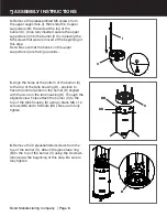
Page 8: ...upwards 6 Remove the 3 preassembled screws from the top of the burner C Attach the glass tube ring B to the top of the burner C using the 3 screws removed at the beginning of this step Be sure to ful...

Page 9: ...the upper supporters I Place the upper reflector A onto the top of the upper supporters I Replace the 3 screws removed at the beginning of this step to secure the upper combination A to the upper sup...

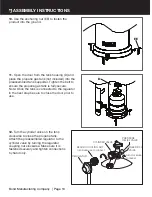
Page 10: ...secure Note Once the tank is connected to the regulator in the next step be sure to close the door prior to use CYLINDER VALVE PRESSURE RELIEF VALVE BLEED OFF VALVE BLACK COUPLING NUT REGULATOR turn...

Page 11: ...ter is on a strong and flat surface The heater may be damaged if the unit tips over Never use the heater if the glass tube shows any cracks Before performing a leak test be sure that no sparks can occ...

Page 12: ...ion control knob to the pilot position hold down for 1 minute 4 Push the ignition button while still holding down control knob down to generate a spark 5 Check to see if there is a pilot light through...

Page 13: ...and inside of the glass tube with soap and water if any carbon deposits are present MAINTENANCE Problem Cause Solution Gas valve may be off Turn the gas valve on Gas tank may be empty Refill the gas t...

Page 14: ...mer service bondmfg com Online www bondmfg com The manufacturer warranty will be voided by and manufacturer disclaims any responsibility for the following actions Modification of the unit and or compo...

Reviews: