User’s Manual
17
If the braking transistor is connected to the terminals marked "A" and "B"
in Figure 3-9, switching resonances caused by the lack of filter
capacitance during precharge will destroy the braking transistor.
3.4.1.2.
R
ESISTOR
C
ONNECTION
The polarity of the resistor connections is not critical; however, it is critical
that the resistor be connected to the proper terminals. Improper hookup
can lead to the resistor being connected directly across the DC bus, which
will cause severe overheating and drive stress.
3.4.1.3.
G
ROUNDING
R
EQUIREMENTS
All units come equipped with either a ground terminal or ground stud that
is connected to the module chassis. Ground the chassis in accordance
with local codes. Typically, the wire gauge will be the same as is used to
ground the attached drive.
3.4.2.
I/O
W
IRING
NOTE!
Terminal strip I/O is prewired to the modular I/O module, and is listed here
only for reference. All I/O operations should be carried out using the
network interface.
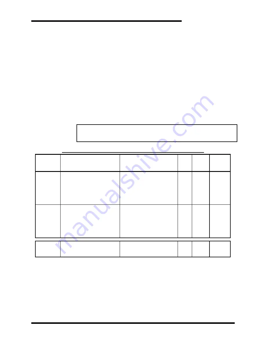
Table 3-2: I/O Terminal Block Specifications: R7 Control Board
T
ERMINAL
F
UNCTION
E
LECTRICAL
S
PECIFICATIONS
(M
AX
)
M
IN
W
IRE
AWG
M
AX
W
IRE
AWG
T
ORQUE
TB1-1
Control Voltage
L1
24V (+)
24V
– 3A *
24V
– 8A *
120V
– 0.6A
230V
– 0.3A
460V
– 0.16A
575V
– 0.15A
16
10
4.5 lb-in
TB1-2
Control Voltage
L2
24V (-)
24V
– 3A *
24V
– 8A *
120V
– 0.6A
230V
– 0.3A
460V
– 0.16A
575V
– 0.15A
16
10
4.5 lb-in
TB2-11&12
Control Signal I/O
Analog
(Note: This signal does not
appear on the network)
18
12
4.5 lb-in
*
24V
– 3A for 200A thru 1200A units. 24V – 8A for 1600A units.
3.4.3.
DC
C
ONTROL
W
IRING
M3452-Dxxx units have 24VDC for control power. This connection is on ASB
3452I5 TB1 with positive in Terminal 1 and negative in Terminal 2. See
Figure 3-9.
Summary of Contents for M3452
Page 14: ...M3452 vR7 EIP PDP 14 This page intentionally left blank ...
Page 19: ...User s Manual 19 Figure 3 2 Customer Connections in K9 Chassis CUSTOMER I 0 CONNECTION ...
Page 21: ...User s Manual 21 Figure 3 2 Customer Connections in M14 Chassis CUSTOMER I O CONNECTION ...
Page 24: ...M3452 vR7 EIP PDP 24 Figure 3 6 I O Hookup with R7 EIP PDP Communication ...
Page 26: ...M3452 vR7 EIP PDP 26 Figure 3 8 24VDC Power Connection ...
Page 58: ...M3452 vR7 EIP PDP 58 This page intentionally left blank ...
Page 66: ...M3452 vR7 EIP PDP 66 Figure 6 3 M3452 K9 Chassis Dimensional Outline Drawing ...
Page 68: ...M3452 vR7 EIP PDP 68 Figure 6 5 M3452 M14 Chassis Dimensional Outline Drawing ...
Page 75: ...User s Manual 75 NOTES ...
Page 76: ...M3452 vR7 EIP PDP 76 This page intentionally left blank ...
Page 77: ......
Page 78: ......
Page 79: ......


