User’s Manual
35
Table 4-3 D-Sub Pin Signal Description
P
IN
S
IGNAL DESCRIPTION
1
SHLD
Shield (Connect to Earth Ground)
2
NC
No Connection
3
A
Data A (TxD/RxD+)
4
RTS
Request To Send
5
GND
RS485 Logic Ground
6
+5V
+5V
7
NC
No Connection
8
B
Data B (TxD/RxD-)
9
NC
No Connection
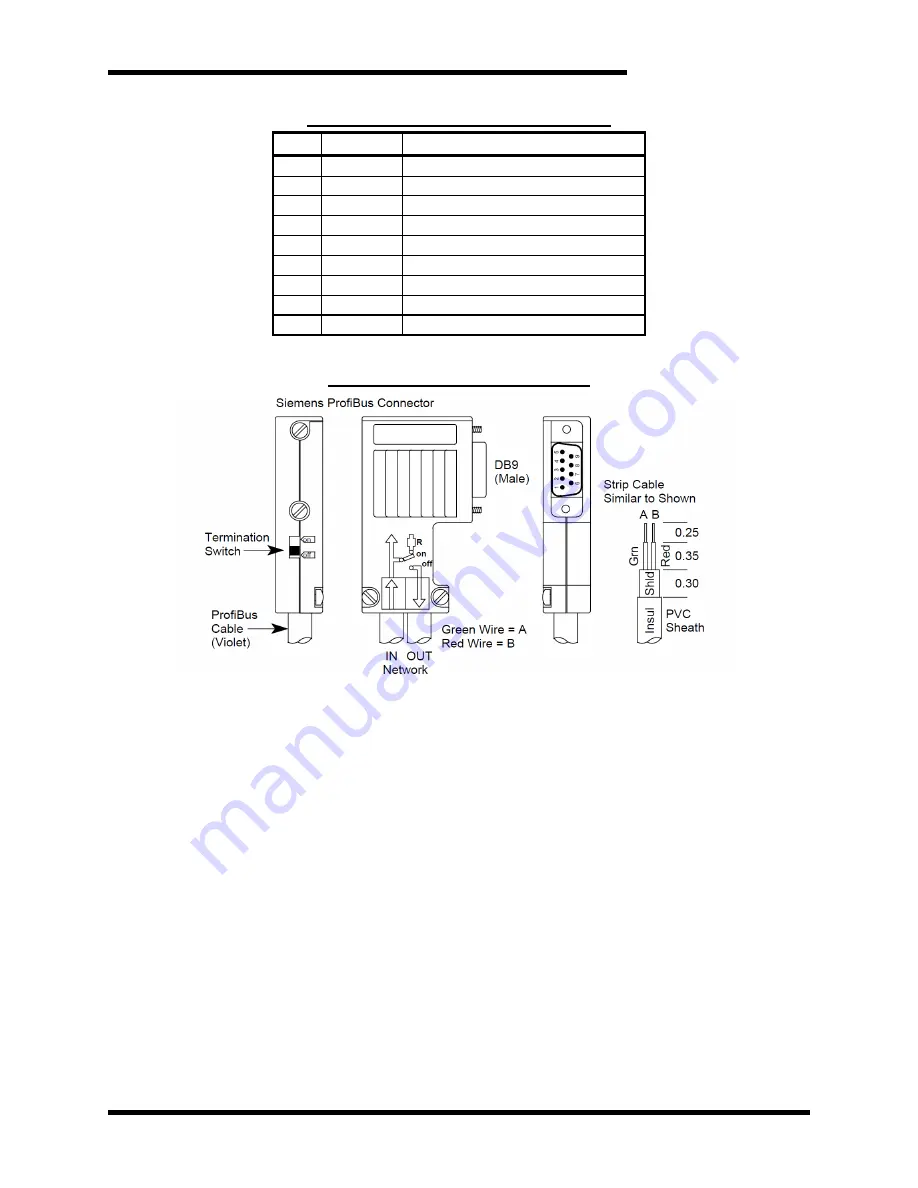
Use PROFIBUS connectors similar to Figure 4-2. (Siemens version shown)
Figure 4-2: PROFIBUS Connector
•
Always use PROFIBUS cable per DIN 19245 and EN 50170.
•
When building cables, do not mix A & B connections. Green
wire is A, red wire is B. The connector must have built in
inductors in order to operate at the higher baud rates.
•
You MUST terminate the network at both ends only.
•
Termination resistors are integrated in the PROFIBUS
connector. When you switch termination ON, the out-going
connections are disconnected from the network.
•
For network
termination, use 220Ω “A” to “B”, plus 390Ω “A” to
GND, and 390Ω “B” to +5V. Use ±2%, 0.25W resistors.
4.2.4.4.4.
N
ETWORK
A
DDRESSING
The network address is set with the two rotary switches on the side
of the PROFIBUS module.
The address stored in the internal EEPROM is modified via the Set
Slave Address command. If the address switches are set to 126 (or
126 to 254) upon power-up, the module will retrieve the last address
stored within its EEPROM (126 from the factory). With both the
internal EEPROM and external switch addresses set to 126, the unit
will await the Set Slave Address command after power-up, before
Summary of Contents for M3452
Page 14: ...M3452 vR7 EIP PDP 14 This page intentionally left blank ...
Page 19: ...User s Manual 19 Figure 3 2 Customer Connections in K9 Chassis CUSTOMER I 0 CONNECTION ...
Page 21: ...User s Manual 21 Figure 3 2 Customer Connections in M14 Chassis CUSTOMER I O CONNECTION ...
Page 24: ...M3452 vR7 EIP PDP 24 Figure 3 6 I O Hookup with R7 EIP PDP Communication ...
Page 26: ...M3452 vR7 EIP PDP 26 Figure 3 8 24VDC Power Connection ...
Page 58: ...M3452 vR7 EIP PDP 58 This page intentionally left blank ...
Page 66: ...M3452 vR7 EIP PDP 66 Figure 6 3 M3452 K9 Chassis Dimensional Outline Drawing ...
Page 68: ...M3452 vR7 EIP PDP 68 Figure 6 5 M3452 M14 Chassis Dimensional Outline Drawing ...
Page 75: ...User s Manual 75 NOTES ...
Page 76: ...M3452 vR7 EIP PDP 76 This page intentionally left blank ...
Page 77: ......
Page 78: ......
Page 79: ......


