M3452 vR7 EIP/PDP
38
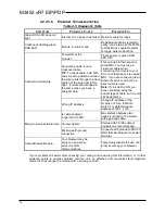
Table 4-4: PROFIBUS Diagnostic Table
S
YMPTOM
P
OSSIBLE
C
AUSE
P
OSSIBLE
F
IX
Yellow Bus LED does not light
Initialization Problem.
LED ON if module in data
exchange state.
Both the internal EEPROM and
external address switches are
set to an address of 126.
•
Check Station Address. Is GSD
file correct. Check for wiring
error.
•
Module awaiting Set Slave
Address command in order to
complete initialization.
•
Alternately, set switches from 0-
125 and re-power.
Cannot communicate.
Power ON at the module and/or
RS485 converter?
Check power. Is green
RUN LED ON?
Is address correct?
Check slave address setting
Is the termination switch of the
PROFIBUS connector at the
prior node turned on?
Switch Termination on only at the
ends of the network. With
termination switch on, the outgoing
connections are disconnected from
the network chain.
Yellow BUS LED turned OFF.
Communication Halted.
Cycle power to reset unit.
Investigate grounding
Continuous flashing green RUN
LED.
Internal firmware problem.
Return module for service.
Many Communication Errors.
Missing Termination Resistors
Termination resistors must be
placed only at both ends of a
network or segment.
Is baud rate too high for
distance?
Maximum distance is limited below
1200 meters as baud rate is
increased above 93.75Kbps (see
Table).
If your problem still exists after checking your wiring and reviewing this information, or if other evidence
points to another problem with the unit, an effective and convenient fault diagnosis method is to
exchange the module with a known good unit.
4.2.4.5.
E
THER
N
ET
/IP
I
NTERFACE
4.2.4.5.1.
G
ENERAL
S
PECIFICATIONS
Interface Standard:
Shielded RJ-45 socket, 8-pin, 10BaseT/
100BaseTX.
Protocol:
EtherNet/IP w/Web Browser Configuration. Unit also
provides 1 socket connection for Modbus TCP/IP..
Data Rate:
Auto-sensed, 10Mbps or 100Mbps.
Duplex:
Auto-negotiated, Full or Half Duplex.
Compliance:
IEEE 802.3, 802.3u, 802.3x.
EtherNet/IP Protocol Support:
Uses built-in web pages for
configuration and control over EtherNet via a standard web browser.
Up to 10 connections via EtherNet/IP and 1 connection via Modbus
TCP/IP (the module uses the standard Modbus TCP/IP socket 502.)
Address:
The module IP address can be preset by the user (static)
and loaded from internal non-volatile memory, or it can be
automatically acquired at startup via a network server using a
BOOTP
(Bootstrap
Protocol),
or
DHCP
(Dynamic
Host
Summary of Contents for M3452
Page 14: ...M3452 vR7 EIP PDP 14 This page intentionally left blank ...
Page 19: ...User s Manual 19 Figure 3 2 Customer Connections in K9 Chassis CUSTOMER I 0 CONNECTION ...
Page 21: ...User s Manual 21 Figure 3 2 Customer Connections in M14 Chassis CUSTOMER I O CONNECTION ...
Page 24: ...M3452 vR7 EIP PDP 24 Figure 3 6 I O Hookup with R7 EIP PDP Communication ...
Page 26: ...M3452 vR7 EIP PDP 26 Figure 3 8 24VDC Power Connection ...
Page 58: ...M3452 vR7 EIP PDP 58 This page intentionally left blank ...
Page 66: ...M3452 vR7 EIP PDP 66 Figure 6 3 M3452 K9 Chassis Dimensional Outline Drawing ...
Page 68: ...M3452 vR7 EIP PDP 68 Figure 6 5 M3452 M14 Chassis Dimensional Outline Drawing ...
Page 75: ...User s Manual 75 NOTES ...
Page 76: ...M3452 vR7 EIP PDP 76 This page intentionally left blank ...
Page 77: ......
Page 78: ......
Page 79: ......


