User’s Manual
51
4.3.
S
TARTUP
WARNING!
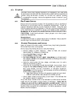
Bonitron heavy duty braking transistors are designed to be used with
stand-alone or common DC bus drive/inverter systems with bus capacitors.
When using the Bonitron modules on common bus systems, special
considerations may apply. Review the Application Notes in Section 7 prior
to start-up!
4.3.1.
P
RE
-P
OWER
C
HECKS
Ensure
that all connections are tight, DC bus polarity is correct, and that all
field wiring is of the proper size for operational requirements. Check for
exposed conductors that may lead to inadvertent contact. Verify the load
bank is properly sized for the application. The ohms value and wattage rating
of the load bank are important for proper and reliable system operation!
Remember: do not operate the module with less than its minimum ohms
value rating!
Verify that the Master / Slave jumpers are in their proper
position for intended use.
M
ASTER
/S
LAVE
In order for the module to operate Stand-Alone, the Master / Slave select bit
must be High. See Section 4.2.4.3.2 for details.
4.3.2.
S
TARTUP
P
ROCEDURE AND
C
HECKS
Apply AC power to the drive system and the heavy duty braking transistor.
Do not start the motors on the system.
On the heavy duty braking transistor, verify the following:
•
Control voltage is within tolerance. Refer to Table 2-6: General
Specifications for voltages and tolerances.
•
Green
Control Power
indicator is
ON
.
•
Amber
DC Bus
indicator is
ON
.
•
Red
Active Braking
indicator is
OFF
!
Immediately
turn off all power if
the indicator is
ON
to avoid possible load bank overheating and/or other
equipment damage!
•
Verify the drive system DC bus voltage, and make sure it is within
tolerance for the drive system.
•
Verify the DC current flow through the load bank is zero amps. Even
though the Red
Active Braking
indicator is
OFF
, any significant current
flow could indicate incorrect connections or damaged equipment.
Immediately turn off all power to avoid possible load bank overheating
and/or other equipment damage!
•
Note: Depending on the type of measuring equipment used, small
currents could just be noise pickup and could be ignored.
•
Check status contacts to ensure they are all closed. This indicates that
the module is ready for operation.
If any of the above conditions are not as indicated, turn off all power and allow
ample time for all system energy sources to discharge.
Verify that all
voltages are zero and have discharged with a suitable meter!
Check all
wiring connections and jumper configurations. Refer to the Troubleshooting
Section of this manual for more information. For further assistance, contact
Bonitron technical support.
Summary of Contents for M3452
Page 14: ...M3452 vR7 EIP PDP 14 This page intentionally left blank ...
Page 19: ...User s Manual 19 Figure 3 2 Customer Connections in K9 Chassis CUSTOMER I 0 CONNECTION ...
Page 21: ...User s Manual 21 Figure 3 2 Customer Connections in M14 Chassis CUSTOMER I O CONNECTION ...
Page 24: ...M3452 vR7 EIP PDP 24 Figure 3 6 I O Hookup with R7 EIP PDP Communication ...
Page 26: ...M3452 vR7 EIP PDP 26 Figure 3 8 24VDC Power Connection ...
Page 58: ...M3452 vR7 EIP PDP 58 This page intentionally left blank ...
Page 66: ...M3452 vR7 EIP PDP 66 Figure 6 3 M3452 K9 Chassis Dimensional Outline Drawing ...
Page 68: ...M3452 vR7 EIP PDP 68 Figure 6 5 M3452 M14 Chassis Dimensional Outline Drawing ...
Page 75: ...User s Manual 75 NOTES ...
Page 76: ...M3452 vR7 EIP PDP 76 This page intentionally left blank ...
Page 77: ......
Page 78: ......
Page 79: ......


