M3452 vR7 EIP/PDP
64
the fuse and reapply power. Further damages could result.
Consult Bonitron if
this situation arises.
If you wish to place fuses in your DC link, coordinate the fuse size with the proper wire
size used in your link as per local codes and regulations. Fast acting semiconductor
type fuses should be used.
6.6.
DC
B
US
L
INK
L
ENGTH
L
IMITS
The distance that the chopper is mounted from the main DC bus filter capacitors within
the drive is limited by the amount of inductance in the connection. During switching,
the inductance in the DC bus between the chopper and capacitors stores energy that
must be absorbed by the snubbing circuit in the chopper.
In general, this distance should be kept to a maximum of 30 feet total (10m), or 15 feet
(5m) for the DC+ link and 15 feet (5m) for the DC- link.
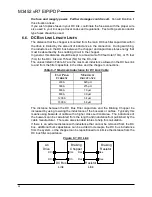
The values listed in Table 6-7 are the maximum inductance allowed in the DC bus link
to and from the filter capacitors in the drive and the chopper connections.
Table 6-7: Maximum Inductance for DC Link Cable
U
NIT
P
EAK
C
URRENT
M
AXIMUM
INDUCTANCE
200 A
620 µH
300 A
275 µH
600 A
70 µH
800 A
39 µH
1200 A
34 µH
1600 A
58 µH
The distance between the DC Bus Filter capacitors and the Braking Chopper be
increased by using lowering the inductance of the buswork or cables. Typically this
means using buswork or cable with a higher cross sectional area. The inductance of
the buswork can be calculated from the length and inductance/foot published by the
cable manufacturer. There are also standard tables to help this calculation.
If there is an extreme distance with inductance that cannot be removed from the DC
bus, additional bulk capacitance can be added to decouple the DC bus inductance
from the system, or the chopper can be repositioned to minimize the distance from the
DC bus filter capacitance.
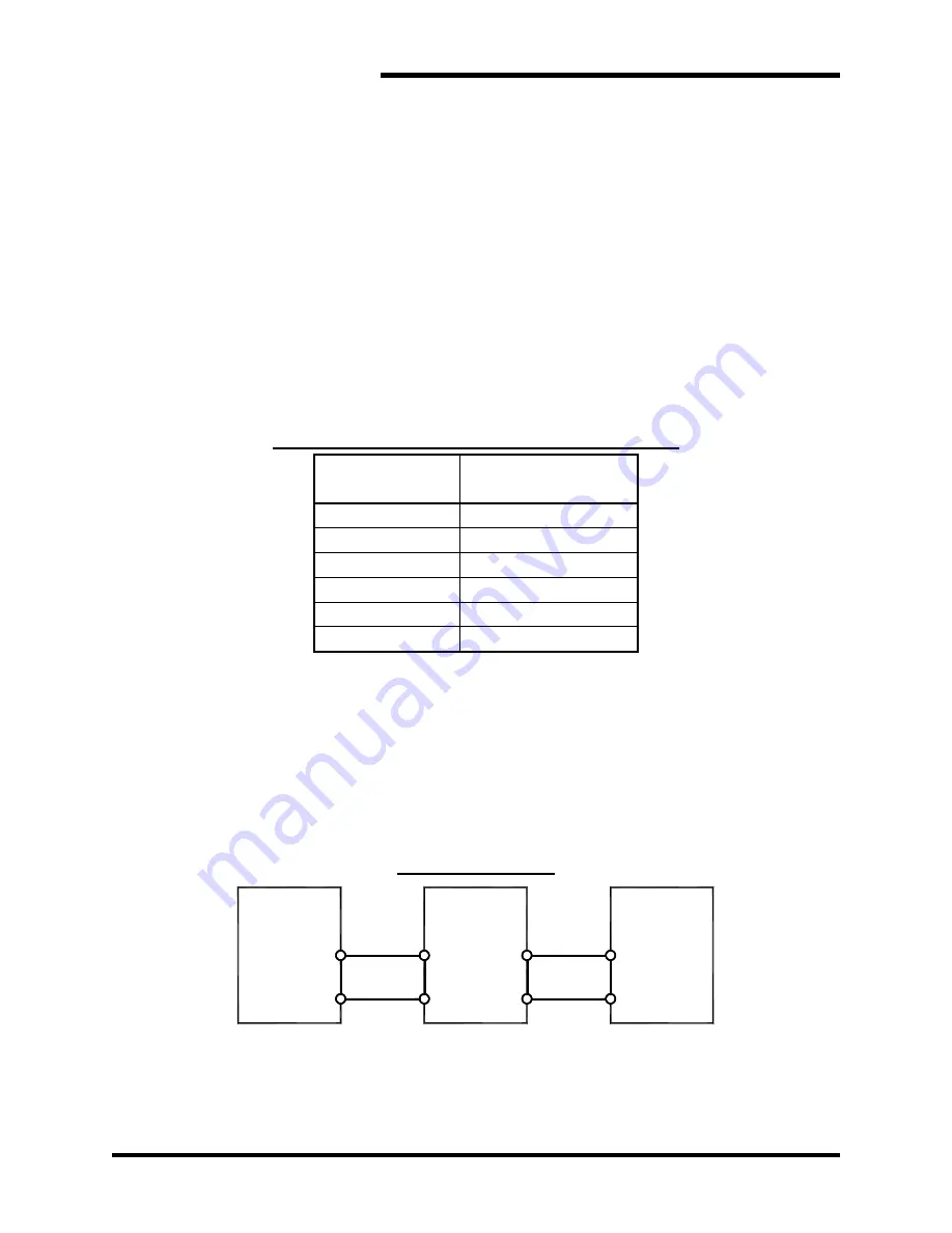
Figure 6-1: DC Link
AC
Drive
DC+
DC-
Braking
Chopper
Res
Res
DC+
DC-
Braking
Resistor
Res
Res
DC Bus
Link
Resistor
Link
Summary of Contents for M3452
Page 14: ...M3452 vR7 EIP PDP 14 This page intentionally left blank ...
Page 19: ...User s Manual 19 Figure 3 2 Customer Connections in K9 Chassis CUSTOMER I 0 CONNECTION ...
Page 21: ...User s Manual 21 Figure 3 2 Customer Connections in M14 Chassis CUSTOMER I O CONNECTION ...
Page 24: ...M3452 vR7 EIP PDP 24 Figure 3 6 I O Hookup with R7 EIP PDP Communication ...
Page 26: ...M3452 vR7 EIP PDP 26 Figure 3 8 24VDC Power Connection ...
Page 58: ...M3452 vR7 EIP PDP 58 This page intentionally left blank ...
Page 66: ...M3452 vR7 EIP PDP 66 Figure 6 3 M3452 K9 Chassis Dimensional Outline Drawing ...
Page 68: ...M3452 vR7 EIP PDP 68 Figure 6 5 M3452 M14 Chassis Dimensional Outline Drawing ...
Page 75: ...User s Manual 75 NOTES ...
Page 76: ...M3452 vR7 EIP PDP 76 This page intentionally left blank ...
Page 77: ......
Page 78: ......
Page 79: ......

