M3452 vR7 EIP/PDP
72
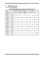
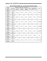
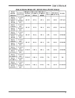
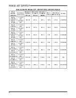
VDC, for 230 VAC systems, it is typically 375 VDC. Refer to your drive
manual for specifics.
For the above example, the ohmic value would be:
ohms
watts
VDC
R
brake
26
.
1
447600
)
750
(
2
=
=
This value must be verified with the ratings of the braking transistor
module selected
that it is not less than the “minimum ohmic value” for that
model. If so, the braking requirements may be more than the braking
transistor module can absorb, and a larger module may be required.
It is also possible to parallel two modules with two separate braking
resistors to achieve the braking power required.
If the ohmic value calculated is greater than the value listed in the ratings
table, it is possible to select a resistor value lower than the calculated
value.
7.1.1.4.
D
UTY
C
YCLE
The duty cycle is based on the amount of time the drive is actually braking
as opposed to accelerating, running at constant speed, or idle. For
instance, if a pick and place operation requires 3 seconds to accelerate,
traverses for 44 seconds and then decelerates for 3 seconds, the total
cycle time is:
sec
50
3
44
3
=
+
+
=
+
+
=
dec
run
acc
cycle
T
T
T
T
The duty cycle for braking is:
%
6
06
.
%
=
=
=
cycle
dec
duty
T
T
This rating assumes the load will be linearly decreasing from peak braking
power to zero braking as the load comes to a stop.
Check this rating against the modules duty cycle rating, and if it is higher
than rated, go to the next higher rated module. If a duty cycle is required
over 50%, please call for assistance with your application.
7.1.1.5.
C
ONTINUOUS
R
ATING
The continuous rating is listed for long term heating calculations should
the unit be installed in an area where heat dissipation is an issue. The
rating is based on a triangular cycle that starts at peak value and reduces
to zero within the rated duty cycle. Therefore, the average braking power
during the deceleration cycle is ½ the power required if full power was
required during the entire braking cycle. This value is:
2
/
%
*
duty
peak
continuous
P
P
=
For the above example, the
W
P
continuous
13428
2
/
%
6
*
447600W
=
=
Summary of Contents for M3452
Page 14: ...M3452 vR7 EIP PDP 14 This page intentionally left blank ...
Page 19: ...User s Manual 19 Figure 3 2 Customer Connections in K9 Chassis CUSTOMER I 0 CONNECTION ...
Page 21: ...User s Manual 21 Figure 3 2 Customer Connections in M14 Chassis CUSTOMER I O CONNECTION ...
Page 24: ...M3452 vR7 EIP PDP 24 Figure 3 6 I O Hookup with R7 EIP PDP Communication ...
Page 26: ...M3452 vR7 EIP PDP 26 Figure 3 8 24VDC Power Connection ...
Page 58: ...M3452 vR7 EIP PDP 58 This page intentionally left blank ...
Page 66: ...M3452 vR7 EIP PDP 66 Figure 6 3 M3452 K9 Chassis Dimensional Outline Drawing ...
Page 68: ...M3452 vR7 EIP PDP 68 Figure 6 5 M3452 M14 Chassis Dimensional Outline Drawing ...
Page 75: ...User s Manual 75 NOTES ...
Page 76: ...M3452 vR7 EIP PDP 76 This page intentionally left blank ...
Page 77: ......
Page 78: ......
Page 79: ......


