Recommended Input Power Wiring Sizes And Power
Source Fusing For Model M3460R Cabinet Mounted And
Rack Mountable Open-Chassis Ride-Thru Systems
doc.#993004
7/18/2000
The following data is supplied for assistance in selecting the appropriate field wiring sizes and
power source fuse ratings for the model M3460R Cabinet Mounted and Open-chassis Ride-Thru
systems.
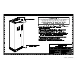
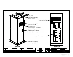
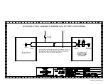
For cabinet mounted systems, the customer power terminations for the 3
∅
AC line and DC
bus are provided on the left side of the cabinet’s ‘disconnect panel’ which is mounted inside at
the upper rear of the cabinet. A ‘Ground’ termination is also provided and is located on the left
side of the cabinet just below the disconnect panel. Refer to
Typical Rack Disconnect Panel
Layout
drawing# 990255
.
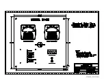
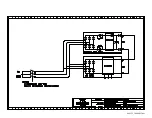
For rack mountable open-chassis systems, Customer power wiring connections to the 3-phase
AC line and DC bus are provided at one end of the Ride-Thru chassis. The 3-phase AC and DC
bus inputs are connected directly to the corresponding fuse mounting terminal. A ground terminal
is provided on the backplate. Refer to
Typical Open Chassis Field Connections Layout
drawing#
000205
.
Please note that the input power source and power wiring supplied to the M3460R Ride-
Thru system must be capable of providing a 2-second surge at twice the rated power of the
Ride-Thru system.
Steady state CLASS J TIME DELAY or equivalent power source fusing should be used to
support the requirement for 2-second surge capability at twice the rating of the Ride-Thru. The
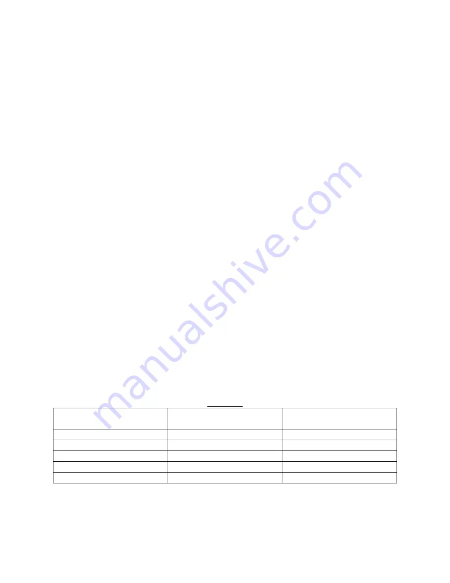
recommended minimum current rating for the power source fusing is listed in Table-1 below
based on the DC bus current rating of the Ride-Thru module. The maximum rating of the steady
state power source fusing should be
≤
225 amps for cabinets with disconnects.
The field wiring sizes listed in Table-1 below assure a
≤
10V drop for wire lengths of
≤
100
feet and are compatible with the recommended steady state power source fusing listed. The wire
gauge selected for field wiring to the Ride-Thru should be equal to or greater than that listed in
Table-1. The maximum wire gauge that can physically be accepted by the cabinet disconnects is
4/0.
Table 1
Ride-Thru DC Bus
Current Rating
Minimum Source Fusing
(Class J Time Delay)
Recommended Field
Wiring Sizes
75 Amps
70 Amps
2 AWG
120 Amps
100 Amps
2 AWG
160 Amps
125 Amps
1 AWG
240 Amps
175 Amps
2/0 AWG
320 Amps
225 Amps
3/0 AWG
Summary of Contents for M3460R
Page 11: ...990078_19990803 doc ...
Page 22: ...970066P_19991230 doc ...
Page 23: ...980265P_19991230 doc ...
Page 25: ...990256_19991022 doc ...
Page 27: ...000122_20000425 doc ...
Page 29: ...990036_19990827 doc ...
Page 30: ...970104_19991025 doc ...
Page 31: ...970103_19981028 doc ...
Page 32: ...990026_19991021 doc ...
Page 33: ...990243_20000712 doc IGBT 150A 1200V IGBT 150A 1200V 150A 1200V IGBT 150A 1200V IGBT ...
Page 34: ...990244_20000712 doc ...
Page 35: ...980233_20000725 doc ...
Page 36: ...970200_20000718 doc ...
Page 37: ... SYSTEM NOTES ...


