User’s Manual
21
DANGER!
The AC control wiring to the 150A, 225A, 300A units is phase sensitive. If
the AC control wiring is not in phase with power wiring catastrophic damage
to equipment will result.
Table 3-5: Power Terminal Specifications
– 150A, 225A, and 300A Unit – M15 Chassis
T
ERMINALS
F
UNCTION
E
LECTRICAL
R
ATINGS
W
IRE
S
IZE
M
INIMUM
W
IRE
S
IZE
M
AXIMUM
T
ORQUE
L1, L2, L3
AC control power
18 AWG
10 AWG
4.4 lb-in
A2, B2, C2
AC line outputs
300 A
350 kcmil
350 kcmil
275 lb-in
DC+, DC-
DC bus inputs
300 A
350 kcmil
350 kcmil
275 lb-in
GND
Ground
3 AWG
1/0
50 lb-in
Notes:
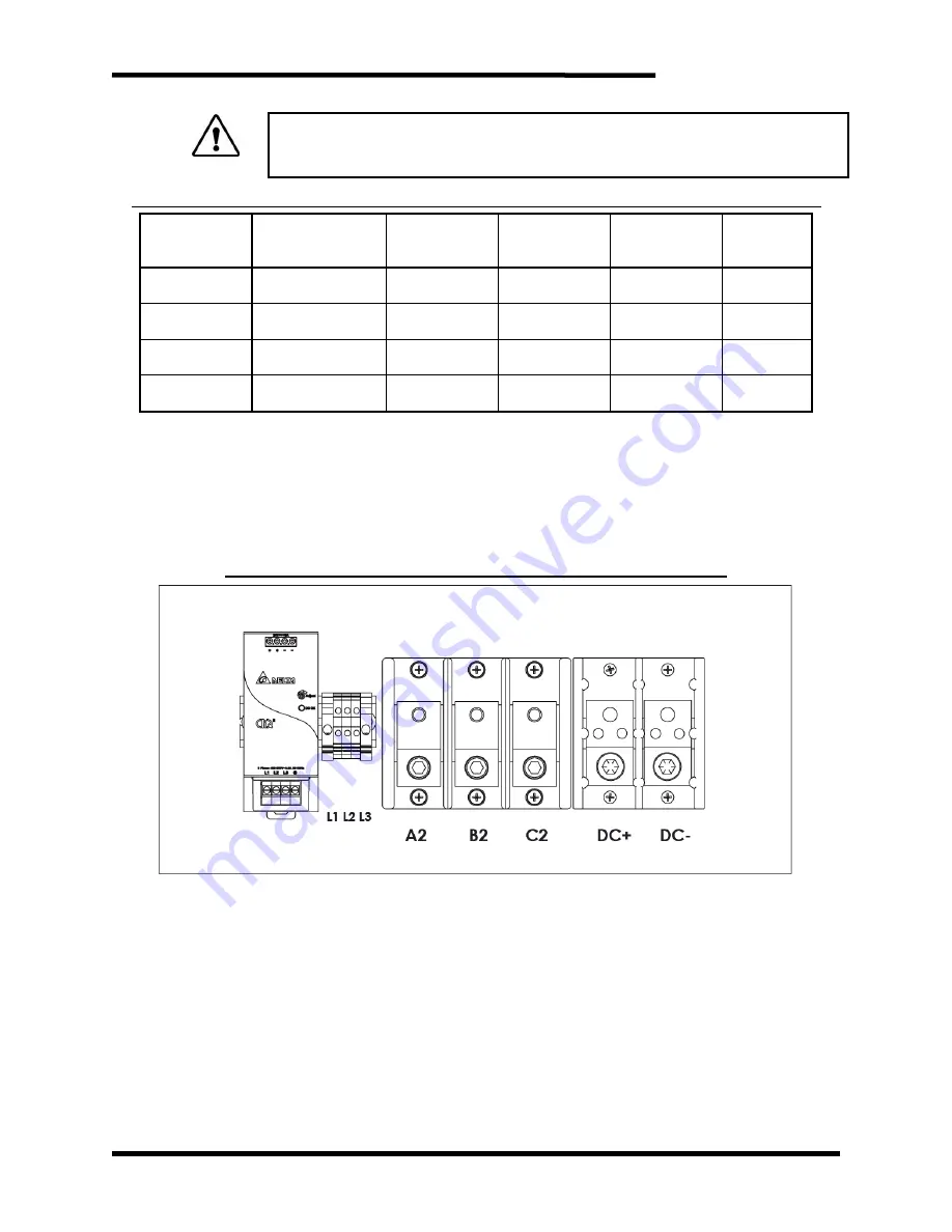
L1, L2, L3 AC control power and A2, B2, C2 AC line output are phase sensitive, switching the order
of phases to any of the inputs may result in damage to the regen. L1 is the same phase as A1. L2
is the same phase as A2. L3 is the same phase as A3.
All power wire should be selected to match or exceed the voltage rating of the unit.
Field wiring for terminals will be copper 75
°
C
wire only.
Figure 3-4: M3645P 150A, 225A, and 300A Power Connections
Summary of Contents for M3645P
Page 14: ...M3645P 14 This page intentionally left blank ...
Page 22: ...M3645P 22 Figure 3 5 M3645P 150A 225A and 300A Connection Locations ...
Page 27: ...User s Manual 27 Figure 3 9 M3645P 150A 225A and 300A Power Wiring ...
Page 30: ...M3645P 30 This page intentionally left blank ...
Page 45: ...User s Manual 45 Figure 6 2 M3645P M11 Chassis Dimensional Outline ...
Page 46: ...M3645P 46 Figure 6 3 M3645P M12 Chassis Dimensional Outline ...
Page 47: ...User s Manual 47 Figure 6 4 M3645P M15 Dimensional Outline ...
Page 48: ...M3645P 48 Figure 6 5 M3645 M15 Line Reactor Dimensional Outline ...
Page 50: ...M3645P 50 6 7 BLOCK DIAGRAM Figure 6 7 Typical Customer Application ...
Page 53: ...User s Manual 53 NOTES ...
Page 54: ...M3645P 54 ...
Page 55: ......


