Instructions n°648261 –
Page 17
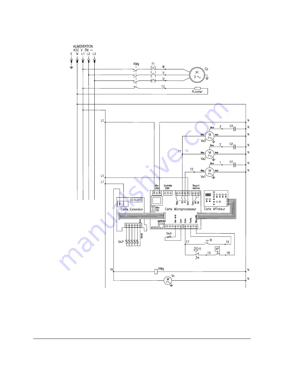
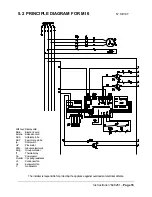
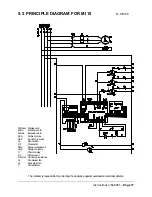
5.3 PRINCIPLE DIAGRAM FOR MI 10
The installer is responsible for protecting the appliance against overloads or electrical defects.
N° SE148
Afficheur : Display card
Micro.
: Electronic card
Extens. : Extension card
Sd.A
: Ambient probe
Sd.P
: 5 point core probe
Ip
: Door switch
HP
: Pressostat
KMg
: Group contactor coil
Kmg
: Group contactor
f1
: Thermal relay
Cp
: Compressor
R carter : Cp casing resistance
Vc
: Condenser fan
Ve
: Evaporator fan
C
: Condensator


