Page
4
of
13
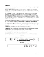
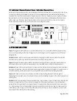
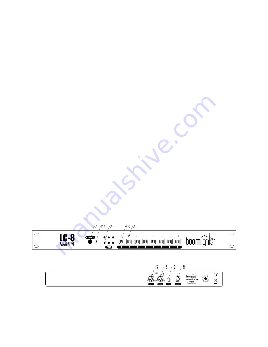
1.2 Features
1 - Power Button:
Pressing this button will turn on the unit. Make sure the power supply is plugged
in and connected to the unit.
2 - Power Indicator Light:
Under normal operating conditions, this indicator light will be green
while the unit is powered on. If the resettable fuse has blown, this indicator light will be red and the
unit will not work.
3 - Test Buttons:
Pressing any of these 3 buttons will test the associated colour on all 8 channels.
For example, if you press the green test button, the green LEDs on all channels will illuminate.
Pressing these
“
Test
”
buttons will not override the colour output of illuminated channels. In other
words, the test button colour will combine with the colour of any illuminated channels. For example,
if you hold down the green test button while all channels are illuminated red, the resultant colour on
all channels will be yellow.
4 - RGB Channel Output Connectors:
Each of these 4-pin USB type B connectors is used for driving
any 12V common anode RGB LED strip.
DO NOT CONNECT TO A USB PORT ON A COMPUTER!
5 - Channel Indicator Light:
Displays the colour output of each RGB channel. These indicator lights
can also be used to monitor a light show remotely or to display a light show without any LED strips
connected.
6 - MIDI In:
Transfers MIDI input signal from a connected source to the unit.
7 - MIDI Thru:
Passes through an exact copy of the MIDI input signal. This allows multiple units or
other MIDI devices to be chained together and controlled by a common source.
8 - Main Resettable Fuse:
When the
unit’s total load
exceeds 8A, this fuse will blow. Reduce the
total load and press and hold the
“
Fuse
”
button to reset the fuse.
9 - DC12V Input:
Main power connection for the unit used to connect the DC12V power supply.
FRONT PANEL
BACK PANEL


