Page
6
of
13
COLOUR
RGB FORMULA
RED
R
GREEN
G
BLUE
B
YELLOW
R + G
MAGENTA
R + B
CYAN
G + B
WHITE
R + G + B
2.3 Changing the Default Settings
2.3.1 Changing the MIDI Note DIP Switches
After removing the
unit’s
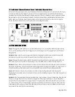
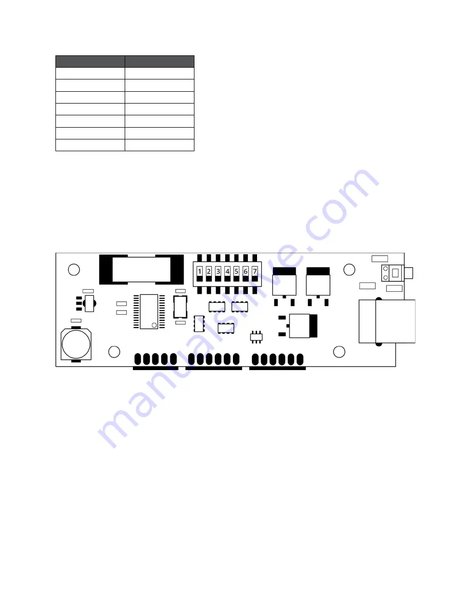
lid, you will notice that each channel has a corresponding vertical circuit
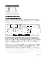
board module. Each channel module has a DIP switch that can be set to various values. Setting the
DIP switch on each channel module determines which MIDI notes that channel will respond to. See
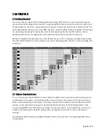
DIP switches 1 through 7 in the diagram below.
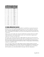
By setting the DIP switches, you are effectively setting the MIDI note that will control the colour
green for that specific channel. The colours red and blue will always be the following 2 MIDI notes.
For example, setting the DIP switches to the binary value 0 (all switches in the down position), means
that this particular module
’s channel
will respond to MIDI notes 0, 1 and 2, which will be green, red
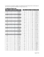
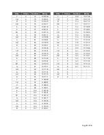
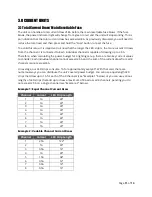
and blue respectively. If you refer to the table in section 2.3.2, you can see the default DIP switch
settings which are highlighted in grey.
To set the DIP switches correctly to the desired MIDI note, refer to the
“Binary”
column on the table
in section 2.3.2. These 7 number sequences represent the individual DIP switch positions. When a
DIP switch is in the up position, i
t is considered “1”
and, when it is in the down position, it is
considered “0”.
These binary codes are used to configure the channel to respond to specific MIDI
notes. For example, if you set only DIP switch number 1 in the up position and leave the 6 remaining
DIP switches in the down position (resulting in the binary code 1000000), MIDI note 64 (E3) will
control the colour green on that particular channel. Therefore, MIDI note 65 (F3) and 66 (F#3) will
control the colours red and blue respectively on the same channel.


