Page
4
of
7
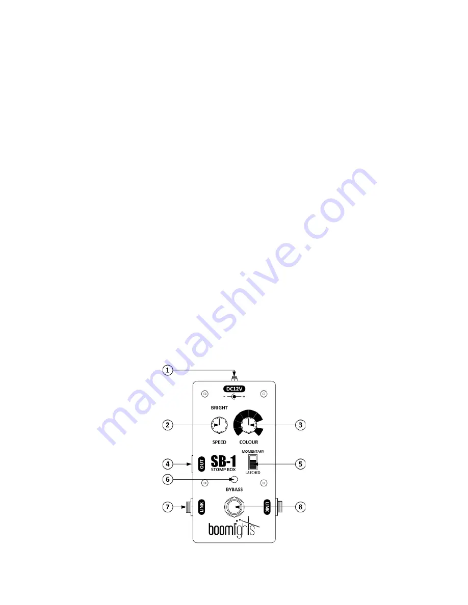
1.2 Features
1 - DC12V Input:
Main power connection for the unit used to connect the DC12V power supply.
2 - Bright / Speed Control Knob:
When one of the 7 fixed colour settings is selected, this knob
adjusts the brightness/intensity of the LEDs. When the variable colour setting is selected, the last
brightness/intensity level will be retained and this knob changes function in order to control the rate
at which the colours randomly cycle.
3 - Colour Control Knob:
This knob is used to select which colour the LEDs will illuminate. There are
7 fixed colour settings (red, green, blue, cyan, yellow, magenta, white) and 1 variable colour setting,
which randomly cycles through all available colours.
4 - RGB Channel Output Connector:
This 4-pin USB type B connector is used for driving any 12V
common anode RGB LED strip.
DO NOT CONNECT TO A USB PORT ON A COMPUTER!
5 - Momentary / Latched Switch:
This switch allows users to select between 2 modes, which
control t
he pedal’s RGB channel output
in different ways
. When the “Momentary” mode is selected,
the RGB channel output will only be engaged while the footswitch is pressed. When the “Latched”
mode is selected, each press of the footswitch will alternate between engaging and bypassing the
RGB channel output.
6 - Bypass Indicator Light:
This indicator light will illuminate red when the RGB channel output is
engaged and will remain unlit when the RGB channel output is bypassed.
7 - Link Jack:
These 1/4
” phono type jacks allow multiple SB
-1 pedals to be chained together. When
connected, any linked SB-1 pedal can be used to simultaneously control all LEDs being driven by all
linked SB-1 pedals.
8 - Pedal Footswitch:
Pressing this footswitch will engage the RGB channel output. The footswitch
will react in correspondence with the control mode selected on the
“
Momentary / Latched
”
switch.


