background image

Studio Electronics Boomstar Manual

50

Panels

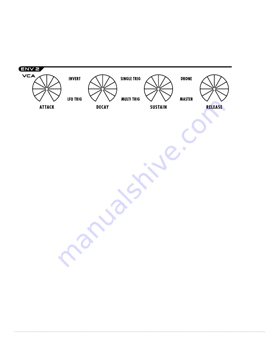
signal is composed of the same four segments: initial rise, decay, sustain 

level, and release time. The volume of the note is shaped according to the 

settings of the envelope controls. These four parameters are shown below.


The 

ATTACK

 knob sets the attack time. The attack time determines the 

duration of the initial rise in volume to a peak. Notice the sound take on 

different qualities as you increase from a short sharp attack to a long slow 

crescendo. Switching 

INVERT 

on reverses the behaviour of the normal ADSR 

envelope... Wait this sound familiar: ENV 2’s invert functions is an exact 

clone (what used to be called a carbon copy) of ENV 1’s. The 

LFO TRIG 

(Low 

Frequency Oscillator Trigger) switch selection phase locks the start of the 

LFO’s wave with the start of the envelope.

The 

DECAY

 knob sets the decay time. The decay time determines the 

duration of the drop in volume from the initial peak to the sustain level. 

Shorter decay times will produce more percussive––snappy sounds, longer 

times “open” up and stretch out the sound, like a good old fashioned 

“woodshedding” session. Switching 

SINGLE TRIG 

(single trigger) on forces the 

decay cycle of both ENV 1 and Env 2 to restart with every key press, or 

note on command. Switching 

MULTI TRIG 

(multiple trigger) on allows for the 

continuation of the decay cycle through a legato, or multi-note phrase.

The 

SUSTAIN

 knob sets the sustain level. The sustain level determines the 

volume level at which the envelope contour levels off after the attack 

and decay. Set at “0,” no sustain level is heard. Set at "5," the contour 

diminishes to a low volume. Set at “10,” no drop in volume is heard after 

the initial peak is reached. Flipping on the 

DRONE 

switch frees up fingers by 

Summary of Contents for 3003

Page 1: ...Studio Electronics Boomstar Manual 1 ...

Page 2: ...tional but highly recommended ANALOGIA INC STUDIO ELECTRONICS will repair or replace where deemed necessary this product at its sole option at no charge to you for parts and labor within the warranty period provided that ANALOGIA INC STUDIO ELECTRONICS reserves the right to determine whether the product is defective for purposes of this Limited Warranty This Warranty does not apply to damage to th...

Page 3: ...ct to change without notice and does not represent a commitment on behalf of ANALOGIA INC No portion of this manual may be produced or transmitted in any form or by any means whether electronic or mechanical or for any purpose other than purchaser s personal use without the explicit written permission of ANALOGIA INC All other products logos or company namesmentionedhereinaretrademarksorregistered...

Page 4: ... 3 2 3 25 Various Templates 15 38 4 Panels 39 58 4 1 Front Panel 39 41 4 1 1 Adjustment Holes 40 41 4 1 1 1 CV 1 Input 40 4 1 1 2 OSC 1 High 40 4 1 1 3 OSC 1 Octave 40 4 1 1 4 OSC 1 Tune 40 4 1 1 5 OSC 1 Scale 40 4 1 1 6 OSC 2 Scale 40 4 1 1 7 OSC 2 Tune 40 4 1 1 8 OSC 2 High 40 4 1 1 9 OSC 2 Octave 40 4 1 1 10 ENV Drive 40 4 1 1 11 VCA Offset 1 41 4 1 1 12 VCA Offset 2 41 4 2 Top Panel 42 56 4 2 ...

Page 5: ...ed Amplifier 53 4 2 10 Master Tune 53 4 2 11 Bend 53 4 2 12 Glide 54 4 2 13 Dynamics 54 4 2 14 ENV 1 PW 1 Envelope 1 to Pulse Width 54 4 2 15 MIXER 54 55 4 2 15 1 VCO 1 Voltage Controlled Oscillator 54 55 4 2 15 2 VCO 2 Voltage Controlled Oscillator 2 55 4 2 15 3 Ring Mod Ring Modulation 55 4 2 15 4 Noise 55 4 2 15 5 Feedback 55 4 2 16 BOOMSTAR SEM Filter Controls 56 4 2 16 1 Notch 56 4 2 16 2 Ban...

Page 6: ...Studio Electronics Boomstar Manual 6 Table of Contents 6 Filter Talkers 63 64 6 1 Bace 63 6 2 Drew Neumann 64 7 The Ancient Chinese 64 8 Back Panel Art 65 ...

Page 7: ... stabilized with temperature compensating resistors placed on top something very similar to what is in an S E M it s gives us just the right amount of warmth and tuning stability The Moog filter employed in all our own synths is a clone except that in the Boomstar 5089 a 3046 replaces the original hand matched transistors in the top and bottom of the ladder The resonance produced is lovely it sits...

Page 8: ...it unplugged from AC outlet This product either alone or in combination with an amplifier and headphones or speakers may be capable of producing sound levels that could cause permanent hearing loss Do not operate for a long period of time at high volume level or at a level that is uncomfortable If you experience any hearing loss or ringing in the ears you should consult an Audiologist Do not place...

Page 9: ...illed into the enclosure through openings Protect the unit from strong jolts and vibration and never apply strong pressure to the front back or side panels or strike them in any manner The product should be serviced by qualified service personnel when A The power supply cord or the plug has been damaged B Solid objects or liquid either have fallen or spilled into the product C The product has been...

Page 10: ... grounding plug which must be plugged into an appropriate outlet that is properly installed and grounded in accordance with all local codes and ordinances DANGER Improper connection of the equipment grounding conductor can result in a risk of electric shock Check with a qualified electrician or serviceman if you are in doubt as to whether the product is properly grounded Do not modify the plug pro...

Page 11: ...ear bottom ofsynth markedPin 1 Com b Plug female 3 prong IEC cable plug into 15 VDC power supply male 3 prong IEC socket c Plug male 3 prong IEC cable plug into AC outlet BOOMSTAR POWER ADAPTER REMOVAL PROCEDURE a Unplug female 3 prong IEC cable plug from 15 VDC power supply b Unplug female 3 prong IEC cable plug from AC outlet c Unplug Boomstar male 15 VDC power supply plug from female connector ...

Page 12: ...th establishes your ownership should there be a legal ownership dispute in the future which then secures access to Analogia Inc Tech Support and Service and if you so desire update information and promotional offers As always our RSS feed News Page Facebook and Twitter outlets are current and update conscious Create and connect to your studioelectronics com account http www studioelectronics com l...

Page 13: ...Studio Electronics Boomstar Manual 13 Setup Essentials 2 5 Signal Flow Chart ...

Page 14: ...oomstar Manual 14 Patch Reset Templates PATCH RESET TEMPLATES 3 1 Home Base We advise starting and returning to this home base when puzzled or lost with this very basic patch to begin your exploration of the Boomstar sound ...

Page 15: ...Studio Electronics Boomstar Manual 15 Patch Reset Templates 3 2 Smoother Circuit Bass Boomstar Manual Rev 1 1 ...

Page 16: ...Studio Electronics Boomstar Manual 16 Patch Reset Templates 3 3 Hardtack Salt Pork Bass Boomstar Manual Rev 1 1 ...

Page 17: ...Studio Electronics Boomstar Manual 17 Patch Reset Templates 3 4 Chirpy 432 Bass Boomstar Manual Rev 1 1 ...

Page 18: ...Studio Electronics Boomstar Manual 18 Patch Reset Templates 3 5 Wonder In Bass Boomstar Manual Rev 1 1 ...

Page 19: ...Studio Electronics Boomstar Manual 19 Patch Reset Templates 3 6 Good Day Gone Bad Bass Boomstar Manual Rev 1 1 ...

Page 20: ...Studio Electronics Boomstar Manual 20 Patch Reset Templates 3 7 Rubbero Bass Boomstar Manual Rev 1 1 ...

Page 21: ...Studio Electronics Boomstar Manual 21 Patch Reset Templates 3 8 Pulsar 2013 Lead Boomstar Manual Rev 1 1 ...

Page 22: ...Studio Electronics Boomstar Manual 22 Patch Reset Templates 3 9 Cleveland Payers Worm Boomstar Manual Rev 1 1 ...

Page 23: ...Studio Electronics Boomstar Manual 23 Patch Reset Templates 3 10 Wurtzite Boron Nitribe Lead Boomstar Manual Rev 1 1 ...

Page 24: ...Studio Electronics Boomstar Manual 24 Patch Reset Templates 3 11 Inverted Envy in Octavo Lead Boomstar Manual Rev 1 1 ...

Page 25: ...Studio Electronics Boomstar Manual 25 Patch Reset Templates 3 12 DNA Breakage Lead Boomstar Manual Rev 1 1 ...

Page 26: ...Studio Electronics Boomstar Manual 26 Patch Reset Templates 3 13 Electrical in Nature Lead Boomstar Manual Rev 1 1 ...

Page 27: ...Studio Electronics Boomstar Manual 27 Patch Reset Templates 3 14 Drew s Kicked Drum Boomstar Manual Rev 1 1 ...

Page 28: ...Studio Electronics Boomstar Manual 28 Patch Reset Templates 3 15 Neuregis Snare Boomstar Manual Rev 1 1 ...

Page 29: ...Studio Electronics Boomstar Manual 29 Patch Reset Templates 3 16 Hihat ala Noise Boomstar Manual Rev 1 1 ...

Page 30: ...Studio Electronics Boomstar Manual 30 Patch Reset Templates 3 17 Aunty s Major Distracted Toms Boomstar Manual Rev 1 1 ...

Page 31: ...Studio Electronics Boomstar Manual 31 Patch Reset Templates 3 18 Lovely Triangle Boomstar Manual Rev 1 1 ...

Page 32: ...Studio Electronics Boomstar Manual 32 Patch Reset Templates 3 19 Clave Mojave Boomstar Manual Rev 1 1 ...

Page 33: ...Studio Electronics Boomstar Manual 33 Patch Reset Templates 3 20 432 FX Boomstar Manual Rev 1 1 ...

Page 34: ...Studio Electronics Boomstar Manual 34 Patch Reset Templates 3 21 3000 Beats per Minute FX Boomstar Manual Rev 1 1 ...

Page 35: ...Studio Electronics Boomstar Manual 35 Patch Reset Templates 3 22 Fibonacci Spiraling FX Boomstar Manual Rev 1 1 ...

Page 36: ...Studio Electronics Boomstar Manual 36 Patch Reset Templates 3 23 Flighted One FX Boomstar Manual Rev 1 1 ...

Page 37: ...Studio Electronics Boomstar Manual 37 Patch Reset Templates 3 24 Sample and Hold in the Park FX Boomstar Manual Rev 1 1 ...

Page 38: ...Studio Electronics Boomstar Manual 38 Patch Reset Templates 3 25 Radiated Greedsters FX Boomstar Manual Rev 1 1 ...

Page 39: ...IMPORTANT WARNING ONLY AN ANALOGIA INC STUDIO ELECTRONICS SUPPLIED PLASTIC SCREWDRIVER OR EXACT EQUIVALENT CAN BE USED TO CHANGE THE BOOMSTAR S FRONT PANEL ADJUSTMENT HOLE SETTINGS TO INSURE UNIT IS NOT DAMAGED BE CERTAIN TO STRICTLY FOLLOW THIS REQUIREMENT THEIMPROPERTOOLANDORUSEOFSAIDTOOLMAYRESULTIN SERIOUS DAMAGE TO SYNTHESIZER AND OR SERIOUS INJURY TO OPERATOR THE OPERATOR OF THIS SYNTHESIZER ...

Page 40: ...ion procedure 4 1 1 4 OSC 1 TUNE For Oscillator 1 tuning calibration procedure 4 1 1 5 OSC 1 SCALE For Oscillator 1 tuning calibration procedure 4 1 1 6 OSC 2 SCALE For Oscillator 2 tuning calibration procedure 4 1 1 7 OSC 2 TUNE For Oscillator 2 tuning calibration procedure 4 1 1 8 OSC 2 HIGH For Oscillator 2 tuning calibration procedure 4 1 1 9 OSC 2 OCTAVE For Oscillator 2 tuning calibration pr...

Page 41: ...nels 4 1 1 11 VCA OFFSET 1 Balances Waveforms very subtle 4 1 1 12 VCA OFFSET 2 De pop MIDI volume or external VCA CV A detailed calibration video will be posted at http studioelectronics com support tutorials boomstar before the end of 4 13 ...

Page 42: ...off CV and Gate work hand in hand to provide the familiar if sometimes floppy and flabby MIDI like ability to control trigger and duration tells the synth you are pressing a note and for how long 4 2 1 3 Voltage Controlled Filter Frequency Modulation Feed a control voltage to externally modulate Filter frequency modulation modulating it with a frequency that is also in the audio range results in a...

Page 43: ...ected raw and gorgeous Send this signal to your DAW or mixer and use liberally or sparingly The purity clarity and transparency of all frequencies concerned is quite apparent and lovely 4 2 1 6 External Input Process any instrument level audio signals including the Boomstar itself patch the OSC OUT to it and beefinate the sound adds additional overdrive distortion more crunchy goodness ...

Page 44: ...ne Sine The most elemental peace seeking waveform with its loner fundamental and no harmonics perfect for sub waveforms simple worms clear clean air and as a sound thickening agent Sawtooth bright buzzy brassy the richest harmonically of the lot a very smooth operator when a low pass filter is inline it contains both even and odd harmonics of the fundamental frequency Square or Pulse A clavi reedy...

Page 45: ...Triangle or Saw with Sine or Pulse Square waveforms center off position switches make it easy The PULSE WIDTH knob sets the width of the Square waveform wide square rectangular forms to narrow nasally tall skyscraper cityscape like shapes A classic Square Wave dials in at the 12 o clock knob setting for that wonderfully warm and yet hollow pulsing rubbery clarinetish tone 4 2 3 VCO 2 Voltage Contr...

Page 46: ... filter or ENV 2 Envelope 2 hard wired to the Amplifier 4 2 4 VCF Voltage Controlled Filter A word about the Filter The Boomstar s four flavor filter system features four classic wide range lowpass filters and in the case of the MINI and 2600 resonant filters The Filter attenuates or cuts off the higher frequency components those which lie above the adjustable cutoff frequency and passes the lower...

Page 47: ...e The resonance or Q emphasizes or boosts the cutoff frequency region and makes the presence of harmonics more apparent The MINI and 2600 filters will begin to self oscillate oscillate and howl or scream like amplifier feedback and may be used as a separate tone source when the resonance value setting passes round 3 o clock Resonance is in fact negative feedback We know this is true because Drew N...

Page 48: ...at one rate falls at a second rate levels off at a certain level and then finally falls off at a third rate These four parameters and their effect upon the cutoff frequency are explained below The ATTACK knob sets the attack time The attack time determines the initial segment of the envelope The frequency at which the contour begins is determined by the filter frequency setting while the peak whic...

Page 49: ...after the initial rise and fall The frequency of the sustain level can be as high as the initial peak in which case there is no decay after the initial rise or it can be as low as the frequency at which the envelope contour began The RELEASE knob sets the release time and is the fourth and final stage of the envelope contour Finally after the initial rise and fall of the attack and decay times to ...

Page 50: ...of the LFO s wave with the start of the envelope The DECAY knob sets the decay time The decay time determines the duration of the drop in volume from the initial peak to the sustain level Shorter decay times will produce more percussive snappy sounds longer times open up and stretch out the sound like a good old fashioned woodshedding session Switching SINGLE TRIG single trigger on forces the deca...

Page 51: ...nd does work after the playing triggering or sequencing is done 4 2 7 X MOD Cross Modulation The VCO 2 DEPTH Voltage Controlled Oscillator 2 Depth sets the amount of Audio Frequency Modulation Use this control in conjunction with Oscillator 2 s frequency to create metallic clangourous planetary searing effects colors and waves Routing VCO 2 s depth through VCO 1 PW Voltage Controlled Oscillator Pu...

Page 52: ...signable to VCO 1 PW VCO 1 FREQ VCO 2 PW VCO 2 FREQ and can be synchronized to MIDI via the MIDI SYNC switch Note In the Filter section the LFO is assignable to filter frequency as well see 4 2 4 Could you break down the LFO features functions again you are asking RATE Sets the speed which approaches audio frequency MIDI SYNC ON locks the LFO rate to clock OFF keeps it local WAVE Selects the wavef...

Page 53: ...se attack decay sustain level and release time the volume of the note is shaped according to the settings of these envelope controls e g an amplifier is used to control the loudness of the sound over a period of time so as to emulate the natural amplitude shape and scope of a real instrument wait a minute an analog synthesizer is a real instrument The OVERDRIVE switch sets the level of overdrive o...

Page 54: ... between notes played OS 2 0 4 2 13 Dynamics Play hard Hear hard Dynamics patches the full 127 steps of MIDI velocity expression of your playing or sequencing to the Filter ENV DEPTH feature of the Filter so Filter Cutoff and Resonance values increase as you heat it up see 4 2 2 4 2 14 ENV 1 PW 1 Envelope 1 to Pulse Width Sets the amount of ENV 1 Envelope 1 level to modulate the pulse width for ma...

Page 55: ... 4 2 15 1 otherwise jack it up 4 2 15 3 Sets the mix or heterodyne of OSC 1 and OSC 2 and outputs the sum and difference of the frequencies present in each waveform techy Expect to hear tones thick in harmonics suitable for producing bell like warm metallic sounds and startpage heterodyne right away along with that other thing you just remembered 4 2 15 4 Sets the mix level of the Noise circuit De...

Page 56: ...3 1 Connections and Switches and Connection Warnings 4 3 1 1 Standard high impedance output 4 3 1 2 The MIDI OUT connection functions as a thru as well The MIDI IN is self explanatory The OVERFLOW switch sets the MIDI overflow parameters for chaining multiple Boomstar synths together Software Rev 2 0 The MIDI LEARN switch accesses settings for modwheel aftertouch note priority LFO key trigger posi...

Page 57: ...HESIZER The proper power connection disconnection procedure and IMPORTANT WARNINGS as previously detailed on pp 11 12 of this manual BOOMSTAR POWER ADAPTER CONNECTION PROCEDURE a Plug Boomstar 15 VDC power supply male 5 pin din plug into female 5 pin din connector mounted on the right side of back panel near bottom ofsynth markedPin 1 Com b Plug female 3 prong IEC cable plug into 15 VDC power supp...

Page 58: ...R AND SUPPLY THE OPERATOR OF THIS SYNTHESIZER ASSUMES ALL RESPONSIBILITY AND LIABILITY ANALOGIA INC STUDIO ELECTRONICS OWNERS OFFICERS AND EMPLOYEES ASSUME NO RESPONSIBILITY OR LIABILITY FOR PERSONAL AND PROPERTY DAMAGE INCURRED DUE TO ACCIDENT CARELESS HANDLING ABUSE OR MISUSE IMPROPER CONNECTION AND OR INSTALLATION IMPROPER ELECTRICAL CONTACT OR GROUNDING OWNERSHIP AND OR USE OF BOOMSTAR SYNTHES...

Page 59: ...s do not allow limitations on the length of an implied warranty or the exclusion or limitation of incidental or consequential damages so the above limitation and or exclusions may not apply to you 5 2 FCC DO NOT MODIFY THE UNIT This product when installed as indicated in the instructions contained in this manual meets FCC requirement Modifications not expressly approved by Analogia Inc Studio Elec...

Page 60: ...occur in all installations If this product is found to be the source of interference which can be determined by turning the unit OFF and ON please try to eliminate the problem by using one of the following measures Relocate either this product or the device that is being affected by the interference Utilize power outlets that are on different branch circuit breaker or fuse circuits or install AC l...

Page 61: ...meets all the requirements of the Canadian Interference Causing Equipment Regulation AVIS Cet appareil numérique de la classe B respecte toutes les exigences du Règlement sur le matériel brouilleur du Canada 5 4 Europe This product complies with the requirements of European Directive 89 336 EEC ...

Page 62: ... Frequency IN Input LFO Low Frequency Oscillator LO Low MOD Modulation MULTI Multiple OSC Oscillator OUT Output PW Pulse Width SYNC Synchronisation TRIG Trigger VCA Voltage Controlled Amplifier VCF Voltage Controlled Filter VCO Voltage Controlled Oscillator WAVE Waveform Glossary of Abbreviations ...

Page 63: ...gher resonance settings that s where most filters reveal their character but there s more The Moog ladder has wonderful overdrive into the filter wide ranging resonance which does reduce gain a little bit as resonance is increased and a sharp 24db slope Warm and fat The 303 is similar to the ladder but one of the stages uses a different capacitor and the resonance is chirpy and mainly available in...

Page 64: ...as anybody mentioned how Boomstar is a play on broom star the ancient Chinese term for a comet That keeps this synth name in the realm of cosmic celestial objects in the grand tradition Thank you controlvoltage this is news to us Our research shows in The Records of the Grand Historian or Shiji or Shi Chi written more than a century later round about midnight on one fine evening day in 100 B C one...

Page 65: ...Studio Electronics Boomstar Manual 65 Back Panel Art ...

Page 66: ...Studio Electronics Boomstar Manual 66 Legal ...

Reviews: