background image


Page: 

52 

OIM - Manual 

Version: 

2014/11


Speedlane 900 

Edition: 

SL900 -OIM - USA


CHANGING OPERATION 

Description of the Frequency Inverter (FI) 

The Frequency Inverter has an integrated control panel, which can be used to configure a number 
of settings. To verify if the product operates properly the display of the module can be used. 
If necessary (e.g. for testing), the drive can also be started, stopped, etc. using the module keys. 
 

NOTE!:

 Normally no changes will have to be made to the Frequency Inverter parameter settings. 

Only in case the factory (Boon Edam) settings are incorrect or have been lost it will be necessary 
to restore the factory (Boon Edam) settings. 
 

9.1  Operation using the integrated control panel 

The integrated control panel provides a quick and easy operation of the Frequency Inverter and 
displays s

everal operational signals and error messages. The “Setting dial” provides a quick and 

direct access to all important drive parameters.  


Control panel 

Summary of Contents for Speedlane 900

Page 1: ...Operation Installation Maintenance Speedlane 900 Version 2014 11 Edition SL900 OIM USA ...

Page 2: ... AND SECURITY SENSORS 10 OPERATION 11 4 Operating concept 11 4 1 OPERATING FUNCTIONS 11 4 1 1 Normally closed mode default setting 11 4 1 2 Normally open mode optional for long Speedlane 900 11 4 1 3 Direction types 12 4 1 4 Access control 12 4 2 SECURITY 12 4 2 1 Intruder alarm 12 4 2 2 Opposite direction alarm 13 4 2 3 Tailgating alarm 13 4 2 4 Low security mode default setting 14 4 2 5 Medium s...

Page 3: ...9 5 5 ANCHORING TO THE FLOOR 30 5 5 1 Anchoring with mounting plates 30 5 6 DOORWING GLASS INSTALLATION 32 5 6 1 Installation of high cabinet glass 33 5 6 2 Options 34 6 Electrical wiring 35 6 1 WIRING BETWEEN THE MASTER AND SLAVE UNIT 35 6 2 EXTERNAL WIRING CONNECTION 35 6 3 WIRE CONNECTION LOCATIONS 35 6 3 1 Internal 35 6 3 2 External 36 7 Microcontroller board 37 7 1 CONNECTIONS TO THE MCB 37 7...

Page 4: ...ee In Out mode 51 8 3 19 Frequency Inverter Model 51 8 3 20 Restore Default Settings Service item 51 CHANGING OPERATION 52 9 Description of the Frequency Inverter FI 52 9 1 OPERATION USING THE INTEGRATED CONTROL PANEL 52 9 2 EXAMPLE OF CHANGING A PARAMETER SETTING 53 9 3 RESTORING FACTORY DEFAULT PARAMETER SETTINGS 54 10 Changing the frequency inverter parameter set 55 10 1 BOON EDAM PARAMETER SET...

Page 5: ...RTER 67 14 4 UPS 68 14 5 OTHER ERRORS 69 TECHNICAL SPECIFICATIONS 70 15 Technical specifications 70 15 1 MOTOR 70 15 2 CONTROL 70 15 3 SENSORS 70 15 4 COMPLETE BARRIER 70 16 APPENDICES 71 16 1 SPARE PART LIST 71 16 2 CHECKLISTS FREQUENCY INVERTER 72 16 2 1 Checklist Frequency Inverter Wide and High Speedlane 900 73 16 3 SOFTWARE UPDATES 74 16 4 MENU STRUCTURE 75 17 Enclosures 76 ...

Page 6: ...9 1 1 Copyright This manual was prepared and issued by Boon Edam All rights are reserved The information in this manual is property of Boon Edam Disclosure of this information or any part of it to third parties is not permitted except with prior and express written permission of Boon Edam 1 2 Liability The product is designed tested and produced in accordance with strict international regulations ...

Page 7: ...id Crystal Display N C Normally Closed LED Light Emitting Diode N O Normally Open MBR Multibeam Receiver PCB Printed Circuit Board MBT Multibeam Transmitter UPS Uninterrupted Power Supply 1 6 Symbols Warnings and cautions WARNING Risk of personal injury or loss of life CAUTION The material may be damaged or the operation of the product affected ...

Page 8: ...ety features without authorization from Boon Edam WARNING Make sure that the dynamic and static forces are within the permissible values See Safety Instruction for further details CAUTION The material may be damaged or the operation of the product affected if the installation procedure is not followed correctly CAUTION Some of the electronic components in the products covered by this manual contai...

Page 9: ... the length of the long Speedlane 900 is 101 9 16 inch or 2580 mm This length is required for proper secure interaction between the sensors and the sliding door wings in the normally open mode The height of the glass door wings of the standard Speedlane 900 is 35 7 16 or 900 mm the height of the high Speedlane 900 is 47 or 1200 55 1 8 or 1400 63 or 1600 70 7 8 inch or 1800 mm This height has been ...

Page 10: ...pre loaded spring unit has been fitted to the wide and wide high versions of the Speedlane 900 to compensate for the weight of the glass panel When the door wing is close to its fully open or closed position the motor has to lift the panel during the final part of the movement The design of the spring construction is such that in the middle position no lift force is generated by the spring In this...

Page 11: ...he transmitters and receivers are operated in such a way that each individual receiver will only respond to its designated transmitter This makes the system insensitive to sunlight fluorescent lighting or other light pollution The Multibeam and MCB communicate through a RS 485 link Children 35 inch or 900 mm are not detected by the security sensors but are detected by the safety sensors between th...

Page 12: ...l system proceeds more quickly than persons are passing the Speedlane 900 a maximum of 3 default value adjustable between 1 and 10 authorizations will be kept in memory Each authorization has a maximum duration of 8 seconds This means that when a person passes the Speedlane 900 the authorization time is reset and the next person gets a maximum authorization time of 8 seconds The door wings remain ...

Page 13: ...ssed in a single direction thus creating a traffic control Free access in both directions The Speedlane 900 can be passed in both directions without authorization It is recommended to select this mode by using the Open functionality Blocked access in both directions The Speedlane 900 cannot be passed 4 1 4 Access control When a person is authorized by the access control system the access control s...

Page 14: ...actually pass the Speedlane 900 on his authorization Opposite direction 4 2 3 Tailgating alarm When an unauthorized person is standing in the Speedlane 900 and a second person is approaching from the same direction the second person can be authorized The first person has to leave the Speedlane 900 at the side the other person is approaching to allow the second person to pass When the unauthorized ...

Page 15: ...d 4 2 6 High security mode When a person who has been authorized to enter the Secure Non Secure zone is closely followed by a second person who has not been authorized the authorized person will be allowed to enter The second person will not The door wings will close after the first person and a sound signal will be activated If the unauthorized person is in the safety zone the door wings will clo...

Page 16: ...n when detecting an obstruction 4 3 2 Mechanical safety In the high security level the door wings will start to open slowly when the door wings close while a person is caught between them and the person can leave the Speedlane 900 After two seconds the door wings will start to close slowly When the door wings remain blocked the sequence of opening and closing will be repeated two more times The bl...

Page 17: ...900 will switch over to the mains power again Emergency power supply 4 3 4 Fire alarm In case of a fire alarm as standard the door wings will open completely allowing free passage through the barrier In case of simultaneous power failure the battery backup will activate this operation When the fire alarm is reset the door wings will slowly turn to their closed position The Speedlane 900 is then re...

Page 18: ...st authorized person has left the Speedlane 900 After the last authorized person the display will be red and the doors will close Alternative signalling When the Speedlane 900 initialises the display on both sides will not be lit If initialising fails after three attempts the display on both sides will blink red When the Speedlane 900 is locked the display will be red on both sides When the Speedl...

Page 19: ...n Malfunction alarm Anti masking detection The Speedlane 900 has an anti masking detection Masking is the condition when one of the sensors is triggered covered continuously for more than 10 seconds When one of the sensors notices masking the acoustic alarm will be activated after ten seconds The alarm continues for three seconds This alarm will also be activated when a person stays to long in the...

Page 20: ...n be switched off or changed to partial mode Partial mode means that the alarm will only be triggered when the intruder is standing in the safety zone of the Speedlane 900 Intruder Door open alarm When the door wings remain open an alarm is given after a number of minutes 4 5 Control panel The Speedlane 900 can be connected to an external control panel Please see the Boon Touch control panel manua...
Page 21: ... a multiple Speedlane 996 also switch off the power of any adjacent Speedlanes CAUTION The material may be damaged or the operation of the product affected CAUTION Before you start the installation check your product on possible options CAUTION Check that all safety devices and systems are fully operational after installation of the door or after maintenance has been carried out ...

Page 22: ...its Basic SAE End wrench set Basic SAE Socket Set SAE Allen Wrench Set Precision Flat Blade Screw Driver 1 5 4mm Hammer Drill with rotary hammer drill bits for concrete anchoring Masonry Anchor Kit 4 Level Tape Measure Electrical Fish Tape for pulling cables Electrical Wire Stripping and Cutting Pliers 4 to 6 Nylon Cable Ties 5 1 3 Anchoring Methods There are many anchoring methods Typically Speed...

Page 23: ...ch can be used to assist in the layout The center of each cabinet will be 35 7 16 900 mm on center of cabinets The distance between the wing panels should be approximately 3 5 32 80mm Always refer to construction drawings for field dimension verification Typical 20 3 32 510 mm Standard lane Floor Dimension Layout Non Secure Side Entry 47 1 4 1200mm 15 11 32 390mm Secure Side Exit 54 29 32 1395mm 3...

Page 24: ...n be used to assist in the layout The center of each cabinet will be 59 1 16 1500 mm on center of cabinets The distance between the wing panels should be approximately 3 5 32 80mm Always refer to construction drawings for field dimension verification Typical 35 13 16 Wide lane Floor Dimension Layout 23 7 32 590mm Non Secure Side Entry 35 13 16 910mm Secure Side Exit MASTER SLAVE 47 1 4 1200mm 54 2...

Page 25: ... the Speedlane 3 x 1 3 4 conduits connecting each Master and Slave unit This is for running the wiring for the sensors motors and LED displays Additionally you will need the following conduits 1 x Conduit to the ACS system This is for the card readers alarm interfacing and lane control 1 x Conduit to the Fire Alarm system 1 x Conduit for Mains Power supply Typical Conduit Layout Secure Side Exit N...

Page 26: ...ct detail and number of conduits Rules to follow when running conduit to multiple lanes Always make sure to run minimum of two 2 1 1 2 conduits between each lane Always verify the proper number and location of conduits for Mains Power ACS Fire Alarm Remote Control Panels and any other interface equipment that may integrate with the Speedlane units Typical Multiple Lane Conduit Layout Secure Side E...

Page 27: ...points The anchoring points for a narrow or wide Speedlane 900 are the same The Speedlane can be directly installed and anchored on the finished floor or with the use of an installation kit Anchoring to Floor Dimension Layout 1 3 16 30mm 9 13 16 250mm 15 3 4 400mm Narrow lane outline Wide lane outline ...

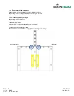
Page 28: ...e top and side panels need to be taken off before anchoring the unit to the floor 5 4 1 Removing top plate To be able to take the side panels out the top plate s need to be removed For all high units the top plate comes in two sections Insert an Allen key wrench and loosen the Allen bolt 1 Lift the end up 2 Pull the top plate 3 Lift the top plate out ...

Page 29: ... USA 5 4 2 Removing Side panel To be able to remove the side panels the top plate s need to be removed first Make sure to remove the earth connection wire 1 Lift the panel up 2 Turn panel out at the inside 3 Move the panel out Be sure to disconnect the Earth PE cable ...

Page 30: ... 4 3 Remove middle section When removing the middle section please make sure to disconnect the sensor wiring as well as the earth connection wire Screw location Screw location Take all four 4 screws and plastic spacers out Remove middle section to gain access to the center ...

Page 31: ... the unit 5 5 1 Anchoring with mounting plates The Speedlane 900 can also be anchored using mounting plates The pictures below will also show a mounting template Mount the plates to the template Position the template at the exact place with the marks on the centerlines and check it with a level Drill the holes for the threaded ends or chemical anchors using the templates The mounting in the floor ...

Page 32: ...ion SL900 OIM USA Place the frame on the mounting plates Check with a level if the frame is correctly placed If this is correct bolt the frame to the mounting plates If not correct use shim plates to level the Speedlane Complete installation of the frame ...

Page 33: ...de the crate The doorwings of the 35 7 16 900 mm high Speedlane will be pre installed in our factory Loosen the three bolts of the clamping strip Before inserting the glass make sure that the plastic ring is installed and that the wax paper is on both sides Insert the glass and tighten the bolts while holding the glass panel in place Check the glass with a level after installation ...

Page 34: ... the high Speedlanes will be delivered separate and needs to be installed on site Loosen the two clamping screws Insert the glass Make sure that The sensor wires are free Cut out in glass is on the correct side Intermediate units have them on both sides Position the glass over the cut out and lower it in Tighten the clamping screws again ...

Page 35: ...l Version 2014 11 Speedlane 900 Edition SL900 OIM USA 5 6 2 Options For the long Speedlane additional tubes need to be installed as shown below Please see project specific drawings for the mounting locations and wiring ...

Page 36: ...e connection 21 x 0 5mm2 or 21 x 20 gauge Motor encoder Authorization LED Traffic LED s 6 2 External wiring connection 1 Mains power 2 Fire alarm contact 3 Access control Authorization pulse in and out Return signals in and out Alarm contacts 4 Control panel 6 3 Wire connection locations 6 3 1 Internal Motor cable The motor in the slave unit will need to be connected directly to the frequency cont...

Page 37: ...ntroller board Fire alarm connector D terminal 15 16 Access control Authorization pulses In and Out are connected directly to the microcontroller board Pulse In connector F terminal 16 17 Pulse Out connector E terminal 16 17 Return Signal In connector F terminal 11 12 Return Signal Out connector E terminal 11 12 Alarm contact can be connected to the relay s General alarm Relay K0 terminal 11 commo...

Page 38: ...es Return signals Control panel Fire alarm Connector A PCB FUNCTION PCB FUNCTION 1 24V 11 CLXA 2 LEDGR1 Green LED secure 12 GND 3 LEDRD1 Red LED secure 13 LNK1 4 24V 14 LNK2 5 LEDGR2 Green LED non secure 15 LNK3 6 LEDRD2 Red LED non secure 16 LNK4 7 24V 17 LNK4 8 ENC_2B Encoder slave B 18 LNK3 9 ENC_2A Encoder slave A 19 LNK2 10 GND 20 LNK1 Connector B PCB FUNCTION PCB FUNCTION 1 24V 11 24V 2 RS1A...

Page 39: ... 9 PU_OUT Pulse sec 19 GND 10 GND 20 GND Connector E PCB FUNCTION PCB FUNCTION 1 24V 11 N C Card reader sec reply 2 5V 12 COM Card reader sec reply 3 GND 13 OPEN Alarm NO 4 OPEN Traffic LED 24V 14 CLOSE Alarm NC 5 CLOSE Traffic LED GND 15 COM Malfunction alarm common 6 COM Traffic green sec 16 IN0 Card reader sec IN 7 OPEN 17 GND Card reader sec GND 8 CLOSE 18 IN1 Traffic non sec 9 COM Traffic red...

Page 40: ...the green light on the transmitting module will remain off and the Multibeam will not work properly Anti masking detection When one of the sensors is triggered covered for more than 10 seconds this is considered to be masking This alarm will also be activated when a person stays to long in the detection sensors When one of the sensors notices masking the acoustic alarm will be activated after ten ...

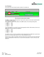
Page 41: ...3 OFF Switch 4 OFF If a second Multibeam is mounted in a long or high Speedlane 900 the 4 DIP switches of the second MBR must be set in the following configuration Switch 1 ON Switch 2 ON Switch 3 OFF Switch 4 ON The RS485 is directly connected to the Microcontroller Board Beside the RS485 this connection also takes care of the power supply 24VDC of the complete Multibeam system On the receiving m...

Page 42: ...tion SL900 OIM USA 7 3 Position of multibeam sensors 7 3 1 Standard model Master 7 3 2 Standard High model Master 7 3 3 Extended High model Master Multibeam 1 Multibeam 2 Multibeam 1 Multibeam 2 Non Secured Secured Non Secured Secured Non Secured Secured ...

Page 43: ...lane have multiple functions Depending on the settings their function changes as well 7 4 1 Closing after passage Depending on the direction In low security mode Sensor 6 or 14 triggers the closing of the wings In medium or high security mode Sensor 7 or 8 sensor 15 or 16 triggers the closing of the wings Non Secured Secured ...

Page 44: ...ode Sensor 1 9 or 7 8 9 15 16 triggers the closing of the wings 7 4 3 Return signal Depending on the authorization direction and passage a return signal can be generated In one direction it is done by sensors 7 1 and the other direction by sensors 15 1 Sequence is Sensor 7 On Sensor 1 On Sensor 7 Off Sensor 1 Off Return signal Sensor 7 is in the other direction sensor 15 Non Secured Secured ...

Page 45: ...Wait for the product to take its starting position Check the security and safety Check the operation of the Speedlane 900 Perform the running in of the Speedlane 900 When a door wing is blocked while it is closing the door will re open automatically and attempt to close 3 times After 3 times the traffic indication signals will blink red When this happens the power needs to be switched off or reset...

Page 46: ...Page 45 OIM Manual Version 2014 11 Speedlane 900 Edition SL900 OIM USA 8 The MCB 8 1 Buttons on the MCB Left Esc Escape Ent Enter Right Reset Program ...

Page 47: ...ed 4 1 1 4 Low security mode 1 Medium and High security mode Sensor usage All All Spare Entry time seconds 8 1 20 Hold time seconds 3 1 20 Reply time deci seconds 3 1 20 Gate open Pulse open Sensor open Pulse open Intruder alarm On On Partial Off Error state Service item Indicates error state Encoder data Service item Displays encoder data Multibeam Service item Displays multibeam state Maximum au...

Page 48: ... Selection Menu jumps back to the second level The same happens in the second level but with a response time of five seconds When the Selection Menu jumps from the second level to the first level the Speedlane 900 will reinitialise and adjustments in parameters will be stored in the memory of the microprocessor 8 3 Menu items 8 3 1 Signalling mode Two types of signalling that can be used standard ...

Page 49: ... additional safety sensor pairs 1 to 5 In case of an extended Speedlane 900 model a further selection has to be made on the number of additional sensor pairs 1 to 4 47 Inch 1200 mm 0 sensor pairs 55 Inch 1400 mm 2 sensor pairs 63 Inch 1600 mm 3 sensor pairs 71 Inch 1800 mm 4 sensor pairs Non standard high versions of the Speedlane 900 will demand different sensor settings If the Speedlane 900 is a...

Page 50: ...ization is lost when stepping out of the Speedlane 900 If the hold time is finished the Speedlane 900 closes normally closed mode The hold time is adjustable from 1 to 20 seconds 8 3 8 Reply time The reply time is the length of a pulse to an access control system when a person has passed the Speedlane 900 The reply time is adjustable from 0 1 to 2 seconds 8 3 9 Gate open In the Gate open selection...

Page 51: ...tem In this menu you can monitor the multibeam state and operation The top row of 16 digits indicates the state of the 16 sensors of the first multibeam and the lower row of the second multibeam A 0 indicates that a sensor is installed A 1 indicates either that no sensor is fitted that the sensor is activated or that the sensor malfunctions A typical display for a high Speedlane 900 with 5 additio...

Page 52: ... direction to pass the Speedlane Special mode When someone enters from the other direction the door wings will close before that person can pass them 8 3 19 Frequency Inverter Model In this menu you can select the model of frequency inverter which is used Mitsubishi FR D or Omron V7 8 3 20 Restore Default Settings Service item It is possible to restore all default settings in the Selection Menu wi...

Page 53: ... started stopped etc using the module keys NOTE Normally no changes will have to be made to the Frequency Inverter parameter settings Only in case the factory Boon Edam settings are incorrect or have been lost it will be necessary to restore the factory Boon Edam settings 9 1 Operation using the integrated control panel The integrated control panel provides a quick and easy operation of the Freque...

Page 54: ...ameter settings of the inverter are controlled via the integrated control panel The selection and setting of the parameters is increased or decreased via the setting dial The example below shows the operational steps for changing the Maximum frequency parameter Pr 1 setting from 120 0 to 50 00 Hz Parameter setting example ...

Page 55: ... The procedure below shows the operational steps for returning the parameter settings of one parameter or all parameters to the factory default of the Frequency Inverter manufacturer NOTE After this factory reset a number of parameters must be set to the Boon Edam BEBV setting See section 10 1 Default parameter settings ...

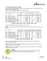
Page 56: ... may be changed It is important to know that not all parameters are given here Each Speedlane 900 type has a different parameter set to give the best operation Type 900 900 H 900 W 900 L 900 HW 900 HL 900 LW 900 HLW Standard X High X X X X Wide X X X X Long X X X X Variations of the Speedlane 900 General parameter description is given No Function Description Unit Pr 00 Start up boost Start up boos...

Page 57: ...meters and range NOTE The parameter settings for the Speedlane 900 Wide are for lanes which have a spring unit installed No Function 900 W LW Default BEBV 900 W LW Setting range 900 HW HLW Default BEBV 900 HW HLW Setting range Pr 00 Start up boost 30 0 30 30 0 30 Pr 01 Maximum speed Hz 80 No range 80 No range Pr 02 Minimum speed Hz 5 No range 5 No range Pr 03 Voltage Pr 19 Freq Hz 26 20 26 26 20 2...

Page 58: ...to upload the Speedlane 900 software into the microprocessor Connect your computer to the communication port on the MCB To enter the programming mode carry out the following steps 1 Press left button and keep pressed 2 Press right button 3 Release right button 4 Release left button The controller is now in the programming mode On the traffic display both the red cross and the green arrow are lit M...

Page 59: ...in correctly there will be no communication possible between the computer and the microprocessor 11 1 1 Field 1 First the communication port must be selected click on the arrow on the right side of the COM Port field Select COM1 Set the Baud Rate to 19200 in the same way Select the device by clicking on the arrow on the right side of the Device field Select XA G49 Set the oscillator frequency to 1...

Page 60: ...croprocessor Use the browse button to select the Hex file 11 1 4 Field 4 In block 4 the Verify after programming option has to be chosen the rest can stay blank 11 1 5 Field 5 Press the Start button to start the uploading Wait till Start is displayed again the program is now ready for another upload to the next microprocessor For each new upload cycle only Start needs to be pressed To leave the pr...

Page 61: ...over plate with the hexagon socket bolt with plastic cylinder Make sure to connect the sensor wiring when installing the middle cover Screw location Screw location 12 2 Side cover After installation of the side covers make sure to connect the Earth cable 1 Move the panel in over the pins 2 Turn panel in at the inside 3 Push the panel down ...

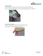
Page 62: ...he top plate s turn the Allen screws out and push the washer out With a one piece top plate place one side over the screw and slowly lower the other side With a two piece top plate Place the center part first and slowly lower the top plate into place Insert an Allen key wrench and tighten the Allen bolt ...

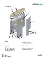
Page 63: ... cover plate non secured side A04 Washer M10 A14 Floor mounting plate small A05 Nut M10 A15 Floor mounting plate big A06 Glass door wing A07 Top plate A08 Cover plate without opening door A18 Hexagon head screw M8 x 30 DIN 933 A09 Cover plate with opening door A19 Plastic cylinder glass mounting A10 Inside cover plate secured side A07 A18 8x A19 8x A09 A10 A13 A12 A08 A03 A11 A04 A05 A06 A14 A15 ...

Page 64: ...he location on the maintenance checklist product type product no In case of malfunctions events can be viewed using in the error state Remove the top plate and side cover to get access to the drive system and electronics Check out with contact and or at reception desk 13 2 Electrical Check the safety functions Perform a function test control panel functions Check the operation of the sensors Check...

Page 65: ...stem pulse X X O length sec 2 Drive d Alarm X O a Motor unit operat noise X O e All functions X X O b Motor mounting bracket X O f Wiring X O c Relays X O g Door wing impact force X X O h Security level Block det X X O 3 Interior i Model Number of sensors X X O a Moving parts X X O j Sensor usage X X O b Bearings X X O k Last action in case of UPS X X O c Internal mounting parts X O d Gate mountin...

Page 66: ... Edam personnel or by an approved agent CAUTION The material may be damaged or the operation of the product affected 14 1 Microcontroller Board Check the fuse when the LCD display of the MCB does not work The fuse is located in the power connector When the fuse appears to be all right the MCB might need to be replaced Try powering down the whole Speedlane 900 by shutting down the UPS and waiting f...

Page 67: ...put fault 40 Opening 41 Opened 42 Closing 43 Closed 5 Grant entry state Card reader entry error 50 Opening 51 Opened 52 Closing 53 Closed 54 Shut 6 Grant exit state Card reader exit error 60 Opening 61 Opened 62 Closing 63 Closed 64 Shut 7 Alarm state Unit in alarm 8 Intruder entry state Check tailgating operation entry 9 Intruder exit state Check tailgating operation exit 1 Stop Check motor 2 Ope...

Page 68: ...t speed Excessive regenerative energy or surge voltage occurred during constant speed Regenerative overvoltage trip during deceleration or stop Excessive regenerative energy or surge voltage occurred during deceleration or stop Motor overload trip electronic thermal relay function Overload or reduced cooling capability during low speed operation Protection from burning due to motor temperature ris...

Page 69: ...period The batteries have run down Recharge them for at least 24 hours by connecting the UPS to the mains Then perform a self test Recharge them for at least 24 hours by connecting the UPS to the mains Then perform a self test Batteries may need to be replaced after a number of years depending on number of discharges and ambient temperature Battery self test failure Battery in a poor condition Rec...

Page 70: ...transmission or slot Door runs too heavy and or FI settings FOUT and VMAX values replace the motor Check the Multibeam status Door turns slowly FI setting Check the value of the parameters n011 to n017 LED s blink red doors are closing and opening continuously alternated with acoustic alarm One of the two angle encoders isn t connected properly Switch A and B signals of one angle encoder Check the...

Page 71: ...24 VDC 100mA Min distance 1m Max distance 10m Temp range 20 C 55 C Response time 20ms 15 4 Complete barrier Type Two wing stainless steel access control barrier with sliding doors Application Barrier that allows controlled access to authorized persons Capacity Controlled access 1 direction nominal capacity 15 to 30 persons minute Combined controlled access in 2 directions Free entry exit nominal c...

Page 72: ...ter FFR CS 050 14A RF1 1 1 50050824 No Break unit Smart Ups 750 VA 1 1 50070147 Multibeam extension cable 1 3m 2 2 50070142 Multibeam Eye transmitter receiver 2 2 65200049 Motor WHD450pwx 120W SL Used before February 2004 1 2 65200051 Motor WHD550pwx 250W SL cable 1mtr 1 2 50080662 Divider module PCB Multibeam SL 1 2 50080661 Sensor module PCB for Multibeam SL 2 4 59772000 Flat cable fem fem 15cm ...

Page 73: ...ion time sec 5 0 0 0 Pr 09 Max premisable Curr A 3 4 0 0 Pr 10 Freq DC braking Hz 3 Pr 11 DC braking time sec 0 5 0 0 Pr 12 DC per of Voltage 4 Pr 17 MRS input selection 0 2 Pr 19 Voltage by Freq Pr 3 V 8888 75 Pr 72 PWM frequency 1 15 Pr 73 Input selection 1 0 Pr 77 Parameter write sel 0 2 Pr 117 PU comm station nr 0 24 Pr 122 PU comm check time sec 0 9999 Pr 125 Terminal 2 gain Hz 50 125 Pr 160 ...

Page 74: ...on time sec 5 0 0 0 Pr 08 Deceleration time sec 5 0 0 0 Pr 09 Max premisable Curr A 3 4 0 0 Pr 10 Freq DC braking Hz 3 Pr 11 DC braking time sec 0 5 0 0 Pr 12 DC per of Voltage 4 Pr 17 MRS input selection 0 2 Pr 19 Voltage by Freq Pr 3 V 8888 75 Pr 72 PWM frequency 1 15 Pr 73 Input selection 1 0 Pr 77 Parameter write sel 0 2 Pr 117 PU comm station nr 0 25 Pr 122 PU comm check time sec 0 9999 Pr 12...

Page 75: ...orks A17 2 Free in bug was solved Mostly free out is used A17 3 This version is used for any wide gate without the spring construction A17 4 After malfunction an auto reset is done when safety sensors 1 7 8 9 15 and 16 are free A18 For any wide gate in combination with the spring construction Maximum retry to close is 5 times Speed change for all wide gates closing speed 1 is not available anymore...

Page 76: ...Page 75 OIM Manual Version 2014 11 Speedlane 900 Edition SL900 OIM USA 16 4 Menu structure ...

Reviews:

Related manuals for Speedlane 900