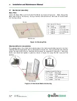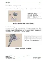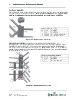
THT-100
22
Boon Edam Inc.
402 McKinney Parkway
Version: Rev A6 10/28//2011
Tel. 910-814-3800 fax 910-814-3899
Issue: THT-100-IMM-USA
5.6 Floor layout
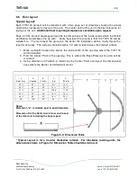
Typical Layout*
Each THT-100 product will be delivered with a two page set of drawings showing the actual
dimensions necessary for layout of the unit. The center point of the unit is the best reference for
laying out the unit.
Additional floor mounting templates are available upon request
.
Page 2 of the product drawings will provide the dimensions of the inside radius which the Shield
and Barrier Assemblies line up with. Verify how level the ground is that the THT-100 will be
installed on. The more level the ground is, the better the installation will be. Verify this with a
level for accuracy. The surface should be within 1/4” (6mm) level across the finished surface.
1. Mark a straight Center Line across the entire width of the opening where the THT-100
will be installed.
2. Find the Center Point of the opening. This is where the Base Plate (pivot point) will be
mounted.
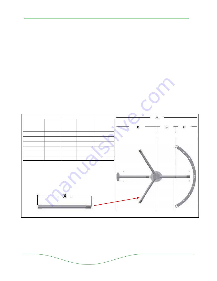
3. Using dimension in Table 5.2, determine the Center Point and layout the dimensional
lines where the Barrier and Shield will mount.
Notes:
Dimension “A” is Outside post to post dimension.
Dimension X of the Rotor Arm is from end to end
of the rotor arm including the square post.
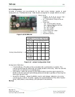
Figure 5-3: Dimension Table
* Typical Layout is for a Counter Clockwise rotation. For Clockwise rotating units, the
dimensions shown in Figure 5.3 Dimension Table should be mirrored.
X
(Rotor Arm)
A
(Opening)
B
(Center)
C
(Arc)
D
(Shield)
22 ¾”
52”
26”
9 ¾”
16 ¼”
24 ¾””
60”
30”
13 ¾”
16 ¼””
27 ¾”
66”
33”
15 5/8”
17 3/8”
30 ¾”
72”
36”
16 ¼”
19 ¾”
38 ¾”
88”
44”
18 ¾”
25 ¼”
48”
106”
52”
23”
29”

