23
Installation and Maintenance Manual
Version : 10//28/2011
Issue
: THT-100-IMM-USA REV A6
5.7 Mechanical Assembly
Base Plate
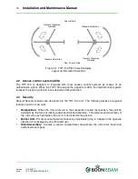
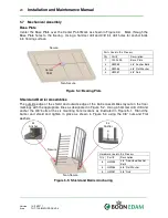
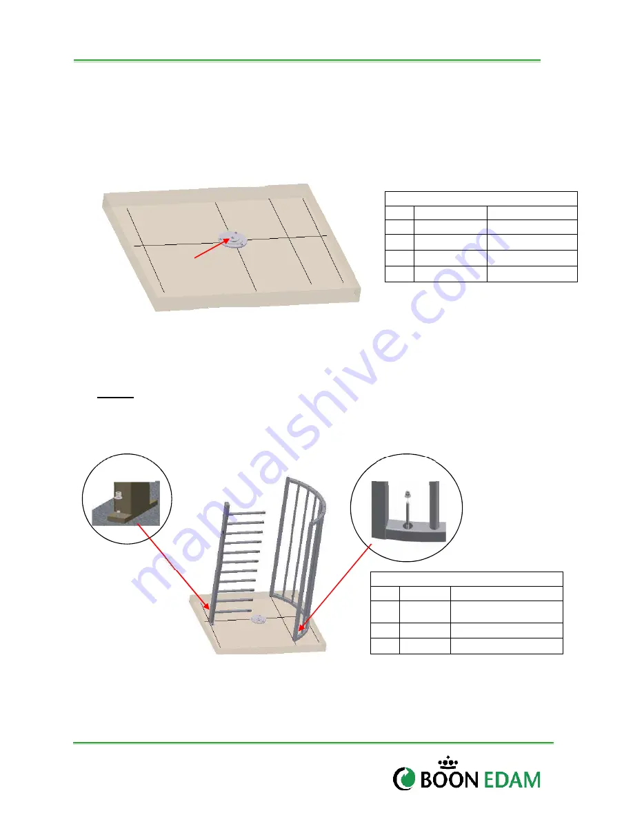
Center the Base Plate over the Center Point Mark as shown in Figure 4.3. Mark through the
Base Plate holes to the flooring. Using a hammer drill and 3/8” bit, drill holes for anchor bolts
into flooring surface.
Figure 5-4: Bearing Plate
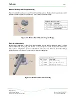
Shield and Barrier Assemblies
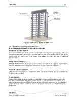
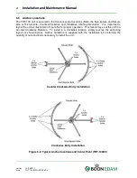
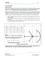
The outside edge of the shield and outside edge of the barrier assemblies layout on the floor
markings with the appropriate lines as designated in Figure 5.2. Using a hammer drill, drill and
anchor the 3/8” bolts at the six mounting hole locations as illustrated in Figure 5.1. Stand the
barrier and shield and tighten in place as shown in Figure 5.4 using the 3/8” nuts and Flat
washers.
Figure 5-5: Shield and Barrier Anchoring
Parts Used in this Process
Qty
Part #
Description
1
100-039E
Base Plate
3
HW055
3/8” Anchor Bolts
3
HW056
3/8” Flat Washer
3
HW057
3/8” Nuts
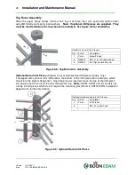
Hardware Used in this Process
Qty
Part #
Description
6
HW055
3/8” Red Head Anchor
Bolts
6
HW056
3/8” Flat Washer
6
HW057
3/8” Nuts
Center
Point
2x
Anchor
4x
Anchor
Non-Secure
Secure
Non-Secure
Secure

