31
Installation and Maintenance Manual
Version : 10//28/2011
Issue
: THT-100-IMM-USA REV A6
5.9 Main Control Box
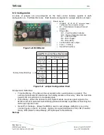
Cable Connections
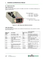
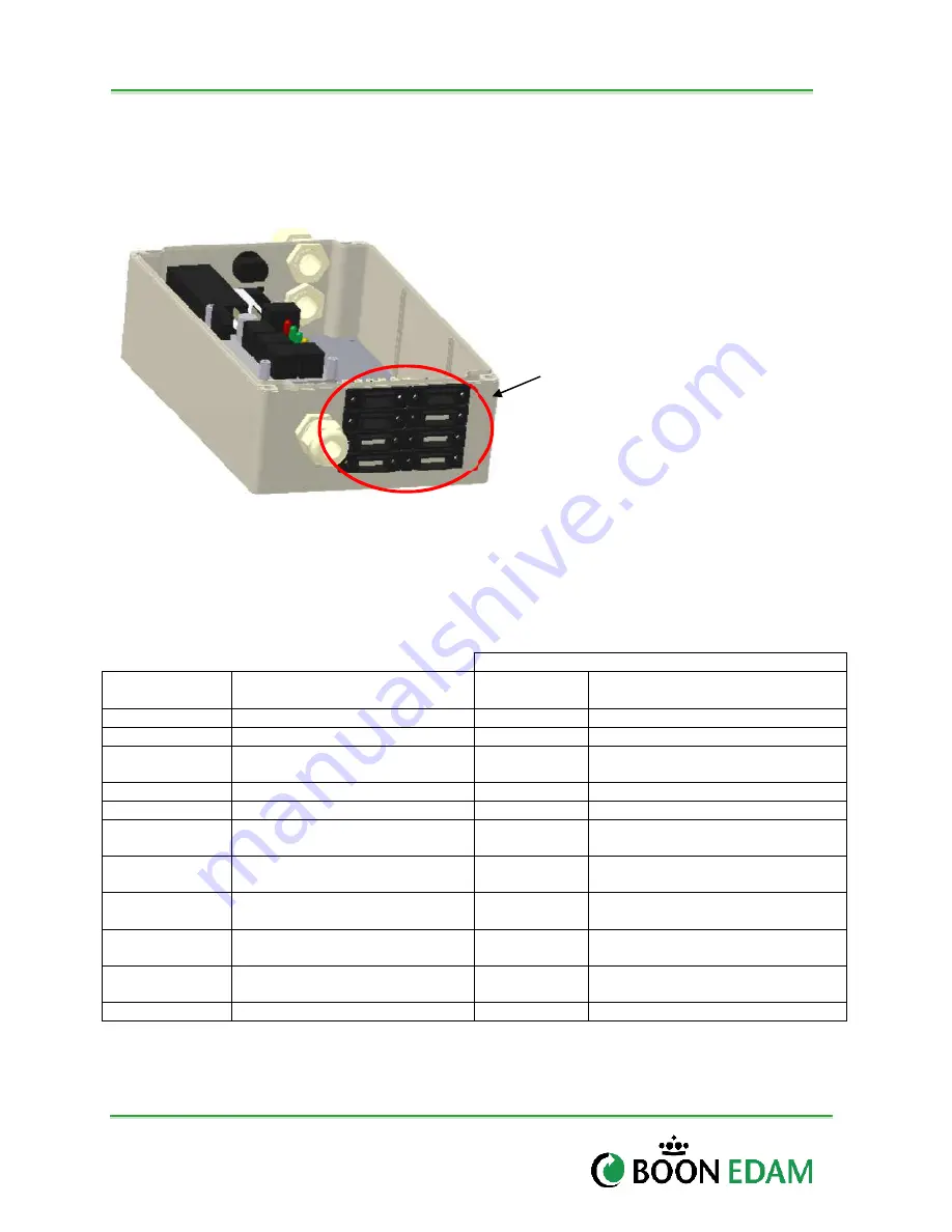
There are many cables which connect to the Main Control Box. The following cable plugs are
typical on the THT-100:
Figure 5-17: Cable Plug Layout of Main Control Box
Cable Descriptions
The following table lists all cables and connecting terminations points of the control box and the
device in the THT-100.
Connection Point
Cable Part
Number
Description
Main Control
Box
Device End
10909
Reset Switch 1 Cable
RS 1
Reset Switch (ACW direction)
10910
Reset Switch 2 Cable
RS 2
Reset Switch (CW direction)
10911
Keyswitch Assembly 1 Cable
KS 1
Keyswitch (Non-Secure) ACW
rotation.
10912
LED 1 Cable
LED 1
LED 1 (Non-Secure Side)
10913
LED 2 Cable
LED 2
LED 2 (Secure Side)
10914
Solenoid Activation Switch 1
Cable
SOL 1
Solenoid (Non-Secure activation
side).
10915
Solenoid Activation Switch 2
Cable
SOL 2
Solenoid (Secure activation side)
10916
Keyswitch Assembly 2 Cable
KS 2
Keyswitch (Secure Side) CW
rotation.
10917
Rotation Detection Switch 1
Cable
Optional
Rotation Detection Microswitch
ACW direction
10918
Rotation Detection Switch 2
Cable
Optional
Rotation Detection Microswitch
CW direction
10919
Home Position Switch Cable
Optional
Home Position Microswitch
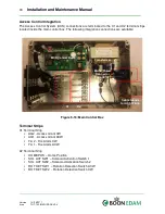
Factory Connected :
•
KS 1 and 2 – Key Switch
•
RS 1 and 2 – Reset Switch
•
Sol 1 and 2 – Solenoids
To be connected in Field:
•
LED 1 and 2 – Endpost Lights
KS 2
RS 2
SOL 2
LED 2
KS 1
RS 1
SOL 1
LED 1

