EN
14
Installation
www.bora.com
Secure the control box
X
X
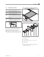
Position the control box [1] with the attached
adjustment plates [2] from the back into the bore
holes in the fixed front panel.
X
Attach the two power level sleeves
[4]
to the front
of the
fixed front panel.
Fig. 5.10 Tighten the fixing nuts
X
X
Screw on the fixing nuts [5] with the mounting bracket
and tighten the fixing nuts with max. 10 Nm.
X
X
Insert the lens from the front into the power level
sleeve.
X
Put on the control knob [
6
].
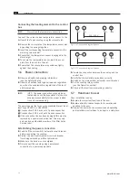
Adjust the control knob
For fine adjustment, the distance between the control
knob and the power level sleeve can be set.
Fig. 5.11 Position control knob
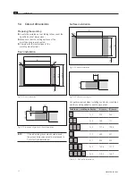
18,5 mm
Fig. 5.12 Distance of the control knob
1
2
90
5
5
>105
37
Ø6
Ø30
Fig. 5.9 Drilling template
[1]
Worktop
[2]
Fixed front panel
X
X
Pre-drill the bore holes to prevent tearing out the fixed
front panel.
Determine the number of adjustment plates
Q
Q
The total dimensions of the adjustment plates [2] and
the fixed front panel [3] should be 36 mm.
Q
Q
The total dimensions of 36 mm must be adhered to in
order to ensure that the control box [1] functions
smoothly.
Panel
thickness
[mm]
Total
thickness
of adjust-
ment
plates
[mm]
Adjustment plates [quantity]
10 mm 5 mm 3 mm 2 mm
34
2
-
-
-
1
33
3
-
-
1
-
32
4
-
-
-
2
31
5
-
-
1
1
30
6
-
-
2
-
29
7
-
1
-
1
28
8
-
1
1
-
27
9
-
1
-
2
26
10
1
-
-
-
25
11
-
1
2
-
24
12
1
-
-
1
23
13
1
-
1
-
22
14
1
-
-
2
21
15
1
1
-
-
20
16
1
-
2
-
19
17
1
1
-
1
18
18
1
1
1
-
17
19
1
1
-
2
16
20
1
1
1
1
15
21
1
1
2
-
14
22
1
1
1
2
13
23
1
1
2
1
Tab. 5.3: Adjustment plate overview
Summary of Contents for PT11UMEN-000
Page 23: ......

