background image

3.7

Boreal Laser Inc. 

GasFinderFCr Operation Manual — Installation  

        July 17th 2017

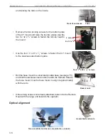
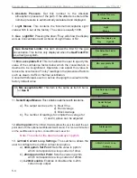
Once the head is fastened, adjust the two alignment screws on the X-Y mount so that the 
retrorefl ector appears in the centre of the cross hairs in the alignment scope. Verify that the 
entire retrorefl ector is clearly visible and there are no obstructions in the path. 

Ensure that the 

GasFinderFCr

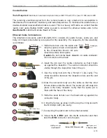
 is switched on and connected to the remote head. Connect the 

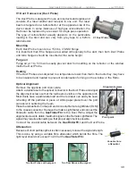
Remote Light Meter (RLM) to the coaxial fi tting on the rear of 
the head. Adjust the X-Y mount with the horizontal and vertical 
adjustment screws so that the reading on the RLM is as high as 
possible. Gently tighten the 4 red locking screws on the mount, 
ensuring that the reading on the RLM does not decrease. 
Note that the RLM will read about 1/10 the value shown at the 

GasFinderFCr.

 A reading below 200 is an indication that more 

refl ectors are required on that path.
A reading greater than 2000 is an indication that the laser signal 
may have to be attenuated. 

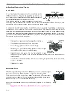
If the retrorefl ector is not visible in the alignment scope or 
diffi culty is experienced getting a reading on the RLM, connect 
the visible laser to the fi bre connector located above the coaxial 
connector.  Switch on the visible laser. Using the continuous 
red beam now being emitted from the Remote Head, the mount 
can be adjusted so that the red beam is refl ected back from 
the retrorefl ector. Verify that the fi bre from the 

Gasfi nderFCr 

is connected and as soon as the RLM registers a reading, the 
visible laser use can be discontinued and the RLM used for 
precise alignment. 

Note: the refl ected beam of the visible laser is very bright and 
should not be observed through the ‘scope.

The red laser output from the aiming laser has very low power 
(conforms to Class 1 as per IEC 60825-1) and will not damage eye tissue. 

However, it is the recommendation of Boreal Laser Inc. that, as with ANY LASER 
SYSTEM, the user/ operator should avoid staring directly into the output aperture of 
the instrument. 

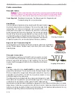
Remote Light Meter

Visible Laser and

Remote Light Meter

Summary of Contents for GasFinder FC

Page 1: ...c GasFinderFCr Operation Manual July 17th 2017 GasFinderFCr Part No NDC 200005 D Menu ver 1 10 c 12846 146 Street NW Edmonton Alberta CANADA T5L 2H7 Phone 1 780 488 5173 Fax 1 780 488 0780 www boreal...

Page 2: ...00010 C GasFinderPT NDC 200021 B GasFinder2 for Multiple Path Monitoring NDC 200025 A User Manuals GasViewOP NDC 200022 B GasViewMC NDC 200013 B GasMap NDC 200007 A Accessory Manuals 4 20mA Module NDC...

Page 3: ...ent Check 2 2 Section 3 Installation 3 1 GasFinderFCr 3 1 Retroreflectors 3 1 Light Values 3 1 Condensation 3 3 Transceivers Remote Heads 3 4 OP1 Remote Head 3 4 OP3 Remote Head 3 5 Optical Alignment...

Page 4: ...and Abbreviations 8 4 Section 9 Appendices 9 1 Appendix A Menu Structure 9 1 Appendix B Status Codes 9 3 Appendix C Explanation of ppmm 9 4 Appendix D Explanation of R2 9 5 Appendix E Conversion from...

Page 5: ...ce Please install in accordance with these instructions WARNING TO REDUCE THE RISK OF ELECTRIC SHOCK Do to expose this equipment to rain or moisture Do not use the unit near water and do not immerse i...

Page 6: ...real Laser Inc GasFinderFCr Operation Manual July 17th 2017 V1 Duct Probe GasFinderFCr mounted in cabinet 2 OP3 Remote Heads in stainless steel enclosures 2 OP1 Remote Heads OP1 Remote Head OP3 Remote...

Page 7: ...derMC GasFinderAB and GasFinderPT laser gas detector products The warranty covers the GasFinder laser analyzers plus Boreal Laser manufactured items supplied with the GasFinder laser analyzers such as...

Page 8: ...jects Extended warranty on GasFinder systems beyond the standard 12 month period PROCEDURES FOR RETURNING A UNIT TO BOREAL LASER Contact Boreal Laser Inc at support boreal laser com or 1 780 488 5173...

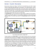
Page 9: ...the GasFinderFCr is sent through a fibreoptic cable to the remote head or duct probe where it is emitted and propagates through the atmosphere to the retroreflector It then returns to the cell where i...

Page 10: ...ad on the front panel or with a computer using GasViewOP These values are described in the Menu Structure which contains three subsections Main Menu contains items such as path lengths units memory et...

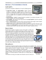
Page 11: ...Belden 9880 Ethernet Cable Patch cord Belden 89907 Accessories OP1 Open Path Transceiver Remote Head Weight 3 0kg 6 6 lb Dimensions L x W x H 315 x 106 x 180mm 12 4 x 4 2 x 7 1ins Power Requirements...

Page 12: ...ignition hazard presented by lasers of this type There are no user serviceable components contained in apparatus all units must be returned to factory for repair Caution The infrared laser output from...

Page 13: ...and limiting paths to 500m for OP3 Remote Heads and be in areas that are safely accessible for installation and maintenance Limit cable runs to 750m or an appropriate distance to pull the cable Dusty...

Page 14: ...ent wrench Small vise grips Phillips Robertson and Flat Head screwdrivers Allen Keys imperial and metric Coaxial cable termination tool Amphenol crimper ARF1118 with CTL 3 jaws 0 100D and 0 429D Wire...

Page 15: ...signal return provided this does not degrade the R2 value Where retro reflectors are used on longer paths these may be mounted in an enclosure on a tripod or the enclosure placed in any convenient loc...

Page 16: ...etros are probably the maximum number that can be economically used as the cost becomes prohibitive as the number of retros increases At path lengths approaching 750m maintaining the correct alignment...

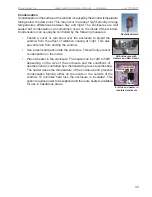
Page 17: ...This also prevents rain from striking the window Use a desiccant pack inside the enclosure This will only prevent condensation on the inside Place a heater in the enclosure The heater can be 12W to 50...

Page 18: ...tate the unit so that the head is aligned with the reflector Tighten the 12mm bolt Remove the 8 screws from the rear plate Connect a visible laser to the fibreoptic laser connector at the rear of the...

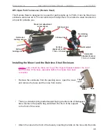
Page 19: ...especially before the shocks have been connected Remove the enclosure from the packing case open the cover and remove the base and the nose from inside There is a tubular spring loaded support laying...

Page 20: ...X Y mount to the stainless steel bottom plate Bolt the base mount to a structurally stable base see page 7 5 and bolt the stainless steel enclosure with the Remote Head to the base mount Use the base...

Page 21: ...than 2000 is an indication that the laser signal may have to be attenuated If the retroreflector is not visible in the alignment scope or difficulty is experienced getting a reading on the RLM connec...

Page 22: ...g the eye laterally will cause the cross hairs to move across the Retro Remove the caps covering the adjustment screws Turn the zoom on the scope to a maximum Focus the eye piece so the retros are sha...

Page 23: ...ted to prevent condensation forming on the window or the Retro Optical Alignment Remove the opposite port cover plate Attach a visible laser to the optical connector in the Duct Probe and adjust the a...

Page 24: ...Kit contains a Remote Light Meter RLM Power Meter Visible Laser Infra Red IR card cables and cleaning tape Fibreoptic Connections The fibreoptic couplings are FC APC and are used to connect two FC AP...

Page 25: ...cuts should be sharp and square Caution Do not nick the braid dielectric or centre conductor Do not comb out the braid 2 Insert the pin over the centre conductor so that it butts up against the dielec...

Page 26: ...are usually spread spectrum type and can transmit data over distances limited by line of sight Cable Connections Power The GasFinderFCr will accept a power source at 100 250V 50 60 440Hz or 120 300V...

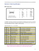
Page 27: ...input from GasFinderFCr 4 PCDTR Data Terminal Ready Serial input from GasFinderFCr 5 GRD Signal Ground Digital Analogue 6 Ramp System Timing Clock Analogue output from GasFinderFCr 7 I sink 4 20mA loo...

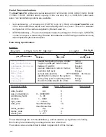
Page 28: ...time ser_number status_code check_sum header designating the type of data String in ppmm parts per million meter Number between 0 and 99 Integer user set distance to retro in metres Number returning l...

Page 29: ...ing is taken from the GasFinderFCr internal clock 4 20mA Option Note that the 4 20mA output is taken from the pins in the DB15 output connector The 4 20mA output is configured using the GasFinderFCr k...

Page 30: ...300m They both require a small amount of power to operate These are two small units one connected to the GasFinderFCr and the other to the computer with a short data cable They are both linked togeth...

Page 31: ...cond baud rate to the correct value typically 9600 Also select 8 data bits no parity and 1 stop bit Flow control should be set to none Click OK If the computer is correctly connected to the GasFinderF...

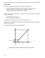
Page 32: ...sually 0 ppmm 4mA and 20mA varies proportionately to the gas concentration 20mA is equivalent to the maximum ppmm or greater If the Distributed Control System DCS is capable of a full 0 20mA resolutio...

Page 33: ...is in the normal operating mode the system will enter the parameter display adjustment menus The arrow keys can be used to move between the various menu items When the operator is in the menu system p...

Page 34: ...he system can operate well with a light value between 2 000 and 12 000 ppm HF R2 Calibrating Light Value Dist 6907 105 5 Concentration units ppm Main Menus Serial HFFC 1012 Version 1 10 c ppm HF R2 1...

Page 35: ...stalled This is not an adjustable item 2 Concentration Units This item displays the units chosen to display the concentration in the main display The units can be adjusted to display ppmm parts per mi...

Page 36: ...Boreal Laser Inc before changing this value from the factory default value 10b Min acceptable R2 This item is the same as item 6 but is for Gas B 11 Serial Output Menus This contains a submenu with tw...

Page 37: ...rds when the memory is full Thus only the latest data is recorded Fill Alternatively if the fill mode is used the data will fill the buffer and once full no new data will be captured Downloading The b...

Page 38: ...d the resulting readings are called sweeps A series of sweeps are averaged to form a scan When the data for the sample scan reference cell scan and associated readings are incorporated into the calcul...

Page 39: ...ry Voltage This provides a convenient way of checking the voltage of the 12V power supply If the voltage falls below 11 5V a flashing B will appear in the top right corner of the display If the voltag...

Page 40: ...h 2017 30 Service Menus This Submenu is only available to qualified personnel and requires a password to enter 31 Password Protected Menus These menus are accessible only for Boreal Laser personnel an...

Page 41: ...on a clear optical path to obtain accurate readings of gas concentration Dust settling on the windows must be cleaned off whenever it degrades the instrument s performance The average value for the l...

Page 42: ...n cleaning them The recommended procedure for cleaning is as follows Blow off any dust using canned compressed air A Note that compressed shop air may contain oil from the compressor and should not be...

Page 43: ...once the obstruction has been removed e g fog lifts rain stops or vehicle equipment is moved No data transmission from GasFinderFCr to the computer Check that the correct baud rate is selected usually...

Page 44: ...k on If the display still shows Cal Err collect an Arrays Transfer File page 7 4 and send it to Boreal Laser together with 30min of data from the gvl text file This will allow Boreal Laser to diagnose...

Page 45: ...ding an array transfer file to an external computer The GasViewOP software can be used to record the file To download the arrays Connect the GasFinderFCr to a computer and run GasViewOP Click on Port...

Page 46: ...centreline before the beam will move completely off the retro array This movement is referred to as translational In practice significant translational movement is unlikely to occur as the post is us...

Page 47: ...o comply with safety regulations the height of a scaffold cannot exceed three times the width of the narrowest base dimension This gives a very stable platform however the alignment will often move sl...

Page 48: ...the metal structure carrying the laser mount which twists with respect to the longitudinal axis of the original laser path This causes the laser beam to move away from the reflectors and results in a...

Page 49: ...the light level drops Note where the cross hairs are in the scope relative to the reflector at these positions see figure 4 and position the head so that the cross hairs are in the centre of the trave...

Page 50: ...7 8 Boreal Laser Inc GasFinderFCr Operation Manual Troubleshooting July 17th 2017...

Page 51: ...principle except that the tube mirrors and crystal are all combined in a small package using semiconductor technology The diode laser is composed of a pn junction as in the light emitting diode LED an...

Page 52: ...c absorption wavelength for this target gas See figure 2 The laser operating wavelength is kept stable by housing it in a temperature controlled box A fluctuating saw tooth current is used to drive th...

Page 53: ...rear behind the glass See figure 4 A retroreflector is different in that the reflected light returns in the same direction as the incident light The beam is reflected 180 degrees A retroreflector is l...

Page 54: ...ntroller A small device using a microcomputer microcomputer A small computer the size of a postage stamp micron 0 000 001 part of a meter modulated Like a wave molecule A collection of atoms bonded to...

Page 55: ...ed A B B only Battery Voltage Gas B Detection Limits enter Adj Gas Type 12 35 A B escape Diabled A B B only esc esc ent esc esc esc esc esc ent esc esc esc ent esc esc esc Internal Temperature Min acc...

Page 56: ...9 2 Boreal Laser Inc GasFinderFCr Operation Manual Appendices July 17th 2017...

Page 57: ...1 1 C 1 1 0 0 D 1 1 0 1 E 1 1 1 0 F 1 1 1 1 n11 n10 n9 n8 Hex n15 n14 n13 n12 0 0 0 0 0 1 0 0 0 1 2 0 0 1 0 3 0 0 1 1 4 0 1 0 0 5 0 1 0 1 6 0 1 1 0 7 0 1 1 1 8 1 0 0 0 9 1 0 0 1 A 1 0 1 0 B 1 0 1 1 C...

Page 58: ...a specific gas such as HF in the path of the laser beam between the transmitter unit and a reflector This is a total path measurement The units are parts per million metres or ppmm A uniform backgrou...

Page 59: ...ed mathematical procedure to compare curves or numeric arrays is the Linear Least Squares Regression analysis This analysis results in a measure of the similarity R2 between the waveform of the sample...

Page 60: ...he signal to noise ratio will increase The general shape of the plot is the same for all gases however the x axis values will depend on the sensitivity of the instrument to the gas species being obser...

Page 61: ...m HF 0 8927 mg m3 at STP STP refers to Standard Atmospheric Pressure P 101 325kPa Standard temperature K 273 15K If the measurement is not taken at STP then an aditional correction is required to adju...

Page 62: ...t item Log to Memory When this is Enabled the internal logging option is activated Log Memory Records This item lists the number of records currently in the memory The storage capacity is 131 072 line...

Page 63: ...ans that the time for one sample is 1 1 second 33 30 50 samples will usually ensure that one reference cell check is included in the calculation The time for a one minute average will be 55 seconds 60...

Page 64: ...of gas which is traceable to NIST standards The calibration data are stored in the instrument s software as a standard reference waveform During operation the GasFinderFCr s internal reference cell is...

Page 65: ...Gas Shift Enable Enable Disable Centre Line Menu Attn Light Compensation output lin menu Min Attn Index Serial Password Protected menu Checked by Light Value Distance Ref Light Ref Cell ppmm Date Data...

Page 66: ...ount Large Boreal X Y Mounta Stainless Steel Enclosure Enclosure for OP3 Remote Head Cables Data Cable Data Cable DB15M DB9F Data Cable DB15M DB9F with 4 20mA pair Fibreoptic Cable Preterminated with...

Page 67: ...he signal by different amounts depending on the length of the cable The value of the compensation is specific to each channel and is entered at the time of commissioning by using the appropriate secti...

Page 68: ...racters to keep the interface lean All commands are terminated by carriage return Enter Commands are responded to using the GasFinderFCr checksummed output line convention GF CER COK n XX where XX is...

Page 69: ...0512FC A 2 GasFinderFCr Dimensions JB0125MC A 3 OP1 Head Overall Dimensions BOR 02110 J 4 OP3 Remote Head Dimensions JB 0930 RH B 5 V1 Duct Probe General DP D V1 001 6 V1 Duct Probe Dimensions DP D V1...

Page 70: ...10 2 Boreal Laser Inc GasFinderFCr Operation Manual Drawings July 17th 2017 This page intentionally left blank...

Page 71: ......

Page 72: ...Boreal Laser Inc GasFinderFCr Operation Manual Drawings January 2011 This page intentionally left blank...

Page 73: ...BOREAL LASER INC MC Instrument Overall Dimensions JB0125MC A 1 of 1 NTS A Dim mm...

Page 74: ...Boreal Laser Inc GasFinderFCr Operation Manual Drawings January 2011 This page intentionally left blank...

Page 75: ......

Page 76: ...Boreal Laser Inc GasFinderFCr Operation Manual Drawings January 2011 This page intentionally left blank...

Page 77: ......

Page 78: ...Boreal Laser Inc GasFinderFCr Operation Manual Drawings January 2011 This page intentionally left blank...

Page 79: ......

Page 80: ...Boreal Laser Inc GasFinderFCr Operation Manual Drawings January 2011 This page intentionally left blank...

Page 81: ......

Page 82: ...Boreal Laser Inc GasFinderFCr Operation Manual Drawings January 2011 This page intentionally left blank...

Page 83: ......

Page 84: ...Boreal Laser Inc GasFinderFCr Operation Manual Drawings January 2011 This page intentionally left blank...

Page 85: ......

Page 86: ...Boreal Laser Inc GasFinderFCr Operation Manual Drawings January 2011 This page intentionally left blank...

Page 87: ......
Page 88: ...Boreal Laser Inc GasFinderFCr Operation Manual Drawings January 2011 This page intentionally left blank...

Reviews: