1.1
Boreal Laser Inc.
GasFinderFCr Operation Manual — System Description
July 17th 2017
Boreal Laser’s patented (US Patent 5,637,872) TDL (Tunable Diode Laser) fi bre coupled
monitor measures gas concentration over an open path. The monitoring system consists
of a rack mounted integrated transmitter/receiver known as the Central Control Unit (CCU),
an open path transceiver head or duct probe, and a remote, passive retrorefl ector array. A
fi breoptic cable connects the CCU to the transceiver head or duct probe. A two-axis instrument
mount and an aiming scope or red aiming laser are used to align the remote head with the
retrorefl ector array. Thr returning laser signal is detected by a photo diode in the remote head
or duct probe and sent back to the CCU via a coaxial cable.
The
GasFinderFCr
is a rack mounted unit 3U high and fi ts in a stanrd 19” rack enclosure.
It houses the laser diode source and microcomputer subsystems and has connectors for
120/240V power input, and data I/O. The remote head or probe is connected with fi breoptic
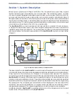
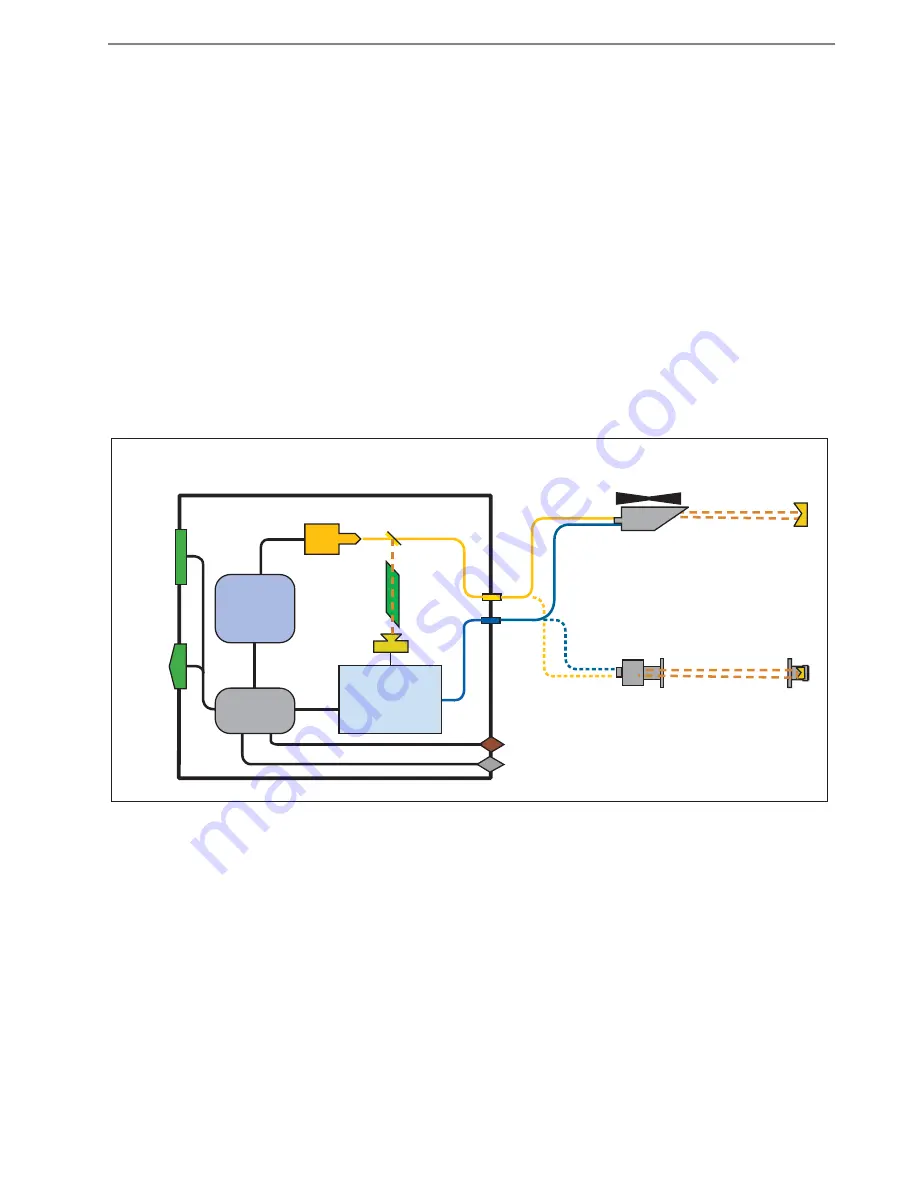
and coaxial cables. A schematic representation of the
GasFinderFCr
system is shown below
in fi gure 1:
The laser signal from the
GasFinderFCr
is sent through a fi breoptic cable to the remote head
or duct probe where it is emitted and propagates through the atmosphere to the retrorefl ector.
It then returns to the cell where it is focused on to a photo diode detector. The detector
converts it to an electrical signal which travels through a coaxial cable to the electronics in the
GasFinderFCr
. A portion of the laser beam is passed through an on board reference cell to
provide a continuous calibration check. These two optical signals are converted into electrical
waveforms which the computer processes to determine the actual concentration of gas along
the optical path. The computed gas concentration is then displayed on the rear panel of the
instrument, and can be transmitted to a computer where the data can be collected, stored,
and graphically displayed. For industrial applications a 4-20mA output is also available.
A software program,
GasViewOP
is available which runs on the computer and can be used
to alter some of the parameters on the
GasFinderFCr
Fig. 1 Schematic representation of GasFinderFCr
Section 1. System Description
Control
Electronics
120/240 Vac input
Data I/O
Keypad
Display
GasFinderFCr
Laser
Diode
Detector
Computer
Calibration
Reference
Cell
Signal
Processing
&
Display
Remote
Retro-reflector
Remote
Retroreflector
Duct Probe
Aiming Scope
Remote
Head
Summary of Contents for GasFinder FC
Page 50: ...7 8 Boreal Laser Inc GasFinderFCr Operation Manual Troubleshooting July 17th 2017...
Page 56: ...9 2 Boreal Laser Inc GasFinderFCr Operation Manual Appendices July 17th 2017...
Page 71: ......
Page 73: ...BOREAL LASER INC MC Instrument Overall Dimensions JB0125MC A 1 of 1 NTS A Dim mm...
Page 75: ......
Page 77: ......
Page 79: ......
Page 81: ......
Page 83: ......
Page 85: ......
Page 87: ......


