background image

NOTE:

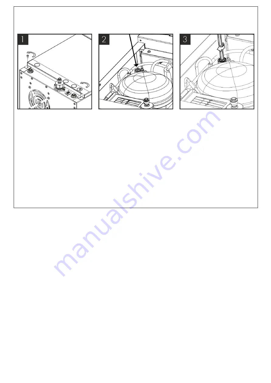
 Sparkling water flow rate factory setting = 2.4L per minute MAX. This may need adjusting 

depending on inlet pressure. To do so follow below steps:

Remove the 2 screws holding

the unit lid down and slide the

lid off. 

Locate the flow control adjuster,

this can be found towards the

front of the unit.

Using a M6 hex key flow can

then be adjusted as follows: turn

the hex key anti-clockwise to

increase flow and clockwise to

restrict flow. After each

adjustment the flow rate should

be timed to an acceptable flow

rate and/or uninterrupted

sparkling dispense

Once the correct flow rate is achieved place the cover back on to the unit by sliding it in place and

replacing the screws.

Summary of Contents for T1

Page 1: ...ce is not suitable for installation in an area where a water jet could be used The appliance has to be placed in a horizontal position WARNING Keep ventilation openings in the appliance enclosure or in the built in structure clear of obstruction WARNING When positioning the appliance ensure the supply cord is not trapped or damaged WARNING Do not locate multiple portable socket outlets or portable...

Page 2: ... be maintained and repaired by authorized technicians who are properly trained and certified Always place the dispenser in its vertical position on a surface which can capably support its weight During use this machine must remain in its upright position Adequate ventilation must be allowed for we recommend using the supplied ventilation ducting kit Keep the machine away from sunlight heat and moi...

Page 3: ...ocal recycling programme Contact your local authority or place of purchase to find out what schemes are available Electrical and electronic equipment contains hazardous substances which when disposed of incorrectly may leak into the ground This can contribute to soil and water pollution which is hazardous to human health and endangers wildlife It is essential that consumers look to re use or recyc...

Page 4: ...Specification ...

Page 5: ...POWER CONSUMPTION CHILLED SPARKLING ProCore 0 20kW 230V MAXIMUM RUNNING POWER CONSUMPTION CHILLED AMBIENT ProCore 0 14kW 230V QUANTITY OF REFRIGERATION GAS R290a 33g POWER SUPPLY 220V 240V AC 50 Hz WATER CONNECTION Mains in 3 4 BSP C02 CONNECTION 1 4 Push Fit DIMENSIONS w x d x h 320 x 370 x 340mm WEIGHT 24Kg RATED CURRENT CHILLED AMBIENT ProCore 1A RATED CURRENT CHILLED AMBIENT SPARKLING ProCore ...

Page 6: ...CLIMATIC CLASS N ...

Page 7: ...roCore unit This is our most discreet range and will fit into any environment seamlessly The ProCore dispenser is a cooler designed to provide chilled and carbonated water All the materials and components are tested during the entire production process in order to satisfy all expectations Model Overview ...

Page 8: ...Contents 1 no T1 with Control Panel 1 no 1 0m x 6mm Insulated Water Pipe 1 no Connector Cable 1 no Fixings Set T1 Tap Major Components Component Feature Overview ...

Page 9: ......

Page 10: ......

Page 11: ...1 Faucet 2 Capacitive touch display 3 Fixing Threads and Bracket 4 Water Outlet Pipe 5 Connector Cable ProCore Electronic Major Components ...

Page 12: ...Contents 1 no Undercounter Unit 1 no 2 0m Power Cord Set 1 no Co2 Regulator with Gauge Connection tube 1 no ProCore Simple fit Ventilation Kit ...

Page 13: ...Handle 5 Top Panel 6 Water Outlet 7 Water Inlet 8 Tap Connection 9 CO2 Inlet 10 On Off Switch 11 Power Connection 12 Side Panel Please Note Mains Installation Kit Filters are supplied as extra items according to individual ordering requirement Sparkling versions only Dimensions ...

Page 14: ......

Page 15: ......

Page 16: ...Installation Requirements Installation ...

Page 17: ...orthern Ireland In territories other than those listed the local regulations in force must be complied with The Water Supply Water Fittings Regulations England Wales and Northern Ireland or The Water Byelaws in Scotland The unit must not be installed where it is liable to freeze If the unit is thought to be frozen it must not be switched on It should be allowed to thaw and must then be thoroughly ...

Page 18: ...ktop is level to allow system to drain Allow for the space needed for forming the required cut out Relate the selected position to the underneath of the counter and check for any obstructions Also allow for the height of the swan neck under any overhanging cupboard shelf Carefully form the needed hole using the correct type of cutter for the work surface material Observe all local occupational hea...

Page 19: ...ispense 3 Chilled Dispense 4 Warning Symbol Basic Functions Dispensing from unit Press and hold dispense icon and release to finish dispense Warning Symbol Warning symbol will illuminate and flash upon a fault Ventilation System Installation Operation ...

Page 20: ... or vent apertures formed in the cabinet to allow an airflow as shown below Normally this should be enough for all situations Important Before making any cuts into the cupboard or kick board ensure the area to be cut is free from water pipes or electrical cables There is a risk of serious injury or death if electrical cables are cut and significant damage to property if a water pipe is cut Using t...

Page 21: ...imney is located correctly in the chimney aperture at the rear of the base After installation the vents at the front of the cabinet and to the sides of the ventilation base must not be obstructed ProCore Installation Water Connection Locate the ProCore in a suitable position using the supplied ventilation base by following the instructions above Connect the T1 tap to the water outlet Connect the T...

Page 22: ... the supply See CO2 Installation section Connect the chiller to the electricity supply The carbonator should be purged of air by activating the sparkling water dispense for approximately 10 seconds Turn on the water supply to fill the tank Allow the machine to stand for 8 12 minutes for the initial chilling process to complete CO2 Bottle Installation Sparkling Versions Only ...

Page 23: ... vent in the stem is facing away from you or anyone else Ensure the regulator is closed Hand tighten securely Connect the assembled CO2 bottle and regulator to the CO2 inlet using a pipe Stand the cylinder in a suitable place We recommend between 3 5 4 bar 58 PSI max Do not exceed 4 bar pressure Sparkling Water Flow Rate Sparkling Versions Only ...

Page 24: ...ol adjuster this can be found towards the front of the unit Using a M6 hex key flow can then be adjusted as follows turn the hex key anti clockwise to increase flow and clockwise to restrict flow After each adjustment the flow rate should be timed to an acceptable flow rate and or uninterrupted sparkling dispense Once the correct flow rate is achieved place the cover back on to the unit by sliding...

Page 25: ...f incoming mains water Briefly press chilled dispense button to release internal water pressure from the machine Remove the existing filter Use Sterizen Hand Gel and put on protective gloves Add 25 ml of Sterizen 30 to a clean and empty service filter cartridge Connect to filter head Turn on incoming water allow service cartridge doser to fill Dispense water using the chilled button Repeat with sp...

Page 26: ...any cosmetic marks as needed Remember to include the drip tray If a Waste Overflow System is fitted empty this and flush through with a small amount of sanitisation fluid if needed When the external cleaning minimum 5 minutes is completed flush the machine using the chilled button with clean water until the dispense water runs clear Repeat briefly with the ambient and sparkling buttons if present ...

Page 27: ...ding metals can cause damage Always rinse all contact surfaces after use with clean water Avoid skin contact and wear protective gloves when handling sanitisation fluids In the event of any skin contact flush immediately with clean cold water Pre flush the new filter to waste using the chilled button until the water appears clear and is free of air Flush through a small amount of water to check al...

Page 28: ...utton until all the water is expelled and only CO2 gas is being released The tank is empty of sparkling water when only CO2 is being released Ensure to release the Sparkling water button and take care to avoid releasing excess amounts of CO2 gas as this may damage the tank ...

Page 29: ...Fault Diagnostics Advanced Troubleshooting ...

Page 30: ...n Carbonator Tank Visit to view steps for purging tank Residue in Carbonator Tank After prolonged use a surface film can develop within the carbonator tank Refer to cleaning and sanitising instructions Warm Drinks Insufficient cooling air flow through the fridge Check that the condenser is not blocked Check supply to cooling fans 230V AC If supply present replace fans If supply not present move on...

Page 31: ...T1 Chilled Ambient Circuit Schematic T1 Chilled Sparkling Circuit Schematic Technical Information ...

Page 32: ...T1 Chilled Ambient Sparkling Circuit Schematic ...

Page 33: ...Water Pathway Chilled Ambient ...

Page 34: ...Water Pathway Chilled Sparkling ...

Page 35: ...Water Pathway Chilled Ambient Sparkling ...

Page 36: ......

Page 37: ...ProCore Exploded Parts Diagram T1 Exploded Parts Diagram Spares ...

Page 38: ......

Page 39: ...S CSA 720260 PCBA Lite Control Board 700721 Top Panel Asm 720117 Right Panel Asm 720113 Left Panel Asm 720045 Front Panel Asm 701537 Pump 700085 Cooling Fan 701343 UV Asm 700922 Flow Switch 701596 UV Control Board Spares List ...

Page 40: ...lbow 462869 8mm Equal Elbow 462360 8mm Equal Tee 462375 5 16 1 4 Elbow 462851 8 6mm Straight Reducer 462857 8 6mm Reducing Elbow 701263 6mm Compensator 462667 8mm Safety Check Valve 462668 1 4 Safety Check Valve Part No Description CA CS CSA 700092 Laminar Flow Outlet 720112 Tap Outlet Polished Metal 701453 Tap Outlet Plated Black 720321 Touch Control Panel Asm CSA 720324 Touch Control Panel Asm C...

Page 41: ......

Page 42: ......

Reviews: