background image

58   |   

u1 Undercounter Systems

 Install & Operation Guide

GB

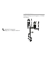
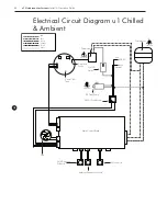
Electrical Circuit Diagram u1 Chilled 

& Ambient

On/Off 
Switch

DC Tank Pump

Detection 

Probe

Fan

Red
Blue
Yellow
Orange
Purple
White

Ambient Dispense Solenoid

Compressor

Cold Dispense 
Solenoid 

Fill Solenoid

Thermostat

DANGER  

HIGH VOLTAGE

24V DC Transformer

Direct Chill 

Tank

DANGER  

HIGH VOLTAGE

Live

DANGER  

HIGH VOLTAGE

230 AC

Inlet

Neutral

Main Control Board

Summary of Contents for u1

Page 1: ... Connection 21 Installation Operation u1 Chilled Ambient Sparkling 22 Major Components 27 Water Connection 28 CO2 Bottle Installation Sparkling Water Operation 33 Sanitisation Guides 37 Trouble Shooting 45 Electrical Measurements Component Diagrams Lists 56 Electrical Circuit Water Pathway Diagrams 62 Certificat Telephone 44 0 1362 695 006 Email sales borgandoverstrom com borgandoverstrom com Syne...

Page 2: ...The manual is intended as a guide only Printed by Borg Overström NR9 5SP UK Copyright Borg Overström ...

Page 3: ...sis Guide 1 2 No Water Dispenses 40 Fault Diagnosis Guide 3 Water Dispenses but not correct Temperature 41 Fault Diagnosis Guide 4 Water Leaks 42 Fault Diagnosis Guide 5 6 Miscellaneous 45 Electrical Measurements Component Diagrams Lists 46 Electrical Test Measurement Values Guide 47 Exploded Component Diagram u1 Chilled Ambient 48 Electrical Wiring Loom Diagram u1 Chilled Ambient 49 u1 Chilled Am...

Page 4: ...4 u1 Undercounter Systems Install Operation Guide GB ...

Page 5: ...u1 Undercounter Systems Install Operation Guide 5 GB Contents 6 Introduction 7 Controls 8 Leak Detection 9 Specification Range Overview Features u1 Undercounter system All Models ...

Page 6: ...his tank is then chilled via the outer evaporation coil of the capillary controlled refrigeration compression system We recommend fitting a Pressure Reducing Valve is fitted to all supplies to regulate the pressure to 3 5 bar 355 kPa u1 Chilled Sparkling and Ambient Models On the carbonated water model water is chilled as it passes through the coil immediately before dispense or being pumped under...

Page 7: ...s Undercounter Unit On Off switch At upper rear of machine Switches Cooling Operation on off Soda switch Switches Sparkling Operation on off Cold Thermostat At rear of machine 10A Fuse On rear of machine integral with IEC socket Top LED Colours to show the Sparkling Operation is switched on Middle LED Colours to show Cooling Mode is switched on Bottom LED Colours to show when compressor is operati...

Page 8: ... indicated by the alarm signalling as also described above To reset Locate the source of leakage and rectify Locate the detection probe which can be found in the bottom front left hand corner Dry the probes and internal area with a dry cloth Unplug the machine and remove the left side plate Locate the Leak Detector valve Reset the red lever push it in Reconnect the power to machine and test operat...

Page 9: ...dent level control fitted inside coil COLD TEMPERATURE 2 C to 11 C THROUGHPUT PER HOUR 18 litres cold 12 C 16 litres sparkling 12 C DISPENSE Swan Neck Faucet with ergonomically designed and situated light touch sensitive controls MAXIMUM RUNNING POWER CONSUMPTION 85 100 watt Cooling Additional intermittent carbonation usage BK5 0 7A BK9 1 5A POWER SUPPLY IEC Power Fused Socket WATER CONNECTION Mai...

Page 10: ...10 u1 Undercounter Systems Install Operation Guide GB ...

Page 11: ...r Systems Install Operation Guide 11 GB Contents 12 Major Components Water Connection 14 Positioning 17 Water Connection 18 Maintenance Removal 19 General Safety Advice Installation Operation u1 Chilled Ambient Model ...

Page 12: ...t Contents Top Cover Side Panels Front Panel Back Panel On Off Mode Switches Thermostat Faucet Connection IEC Power Fused Socket Water out Connections Water in Connections LED Indication u1 Chilled Ambient 1 no Undercounter Unit 1 no 2 0m Power Cord Set 1 no 1 0m Faucet Connection Harness ...

Page 13: ...ctronic Swan Neck Faucet 1 no 2 Button Membrane Switch 1 no 1 0m x 6mm Insulated Water Pipe Also Included 1 no 2 0m x 1 4 Faucet Connection Pipe 1 no 1 0m Faucet Connection Pipe Insulation 2 no 1 4 Stem Elbow 1 no 1 4 Y Fitting 1 no 1 4 Male Threaded Adaptor 1 no 6mm Female Threaded Adaptor Please Note Mains Installation Kit Filters are supplied as extra items according to individual ordering requ...

Page 14: ...otected When positioning to drain over an existing sink bowl allow for the reach of the swan neck or otherwise the position of any optional drip tray When planning and providing for the connection to the services always allow for easily accessible service isolator fittings and for the position of an external water filter Identify a suitable position for the swan neck faucet A 33 35mm max hole is r...

Page 15: ... hole using the correct type of cutter for the work surface material Observe all local occupational health and safety requirements Allow for the space needed for forming the required hole Relate the selected position to the underneath of the counter and check for any obstructions Position the unit in place ensuring it is level and stable Remove the back nut and washer from the faucet and carefully...

Page 16: ... not turn the water supply on at this stage The maximum recommended inlet pressure is 3 5bar We recommend fitting a check valve a pressure reducing valve and a Waterblock device These are available as part of our optional Installation Kit When fitting a Waterblock device we recommend a minimum setting of 2 be used Pre flush and fit the filter in an accessible position 17 15 16 ...

Page 17: ...immediate whining noise from the DC pump should soon stop as the water level in the system rises Fit the male threaded adaptor fitting and the female threaded adaptor fitting Turn on the water supply and check for any leaks Upon the filling cycle completing proceed to flush the cold and the ambient water channels using these buttons on the faucet control panel We recommend that a minimum of 10lts ...

Page 18: ... Water Indicator COLD Switch on the Cooling Mode and allow up to 1 hr for the initial cooling cycle 10 Maintenance Removal 1 2 3 Please make sure the machine is completely disconnected from electricity before carrying out any maintenance work Turn off the water supply To drain the Direct Chill tank remove the cap on the back of the machine We recommend it is refitted immediately upon draining bein...

Page 19: ...ensure there is adequate airflow around the unit Additional ventilation grills or extraction may be required 150mm Keep the machine away from sunlight heat and moisture Be sure to use single outlet socket with correct power voltage Plug the power cord directly into the electrical socket 3 ...

Page 20: ...20 u1 Undercounter Systems Install Operation Guide GB ...

Page 21: ...ontents 21 Major Components 24 Positioning 27 Water Connection 28 CO2 Bottle Installation Sparkling Water Operation 29 Maintenance and Removal 30 Emptying the Carbonation Tank 31 General Safety Advice Installation Operation u1 Chilled Ambient Sparking Model ...

Page 22: ...Front Panel Back Panel On Off Mode Switches Thermostat Faucet Connection IEC Power Fused Socket Water out Connections Water in CO2 in Connections LED Indication u1 Chilled Ambient Sparkling 1 no Undercounter Unit 1 no 2 0m Power Cord Set 1 no 1 0m Faucet Connection Harness 1 no CO2 Regulator with Gauge Carbonation Switch ...

Page 23: ...nic Swan Neck Faucet Contents u1 Chilled Ambient Sparkling 1 no Electronic Swan Neck Faucet 1 no 3 Button Membrane Switch 1 no 1 0m x 6mm Insulated Water Pipe Also Included 1 no 3 0m x 1 4 Faucet Connection Pipe 1 no 2 0m Faucet Connection Pipe Insulation 5 no 1 4 Stem Elbow 1 no 1 4 Cross Fitting 1 no 1 4 Male Threaded Adaptor 1 no 6mm Female Threaded Adaptor Major Components ...

Page 24: ...otected When positioning to drain over an existing sink bowl allow for the reach of the swan neck or otherwise the position of any optional drip tray When planning and providing for the connection to the services always allow for easily accessible service isolator fittings and for the position of an external water filter Identify a suitable position for the swan neck faucet A 33 35mm max hole is r...

Page 25: ... hole using the correct type of cutter for the work surface material Observe all local occupational health and safety requirements Allow for the space needed for forming the required hole Relate the selected position to the underneath of the counter and check for any obstructions Position the unit in place ensuring it is level and stable Remove the back nut and washer from the faucet and carefully...

Page 26: ... not turn the water supply on at this stage The maximum recommended inlet pressure is 3 5bar We recommend fitting a check valve a pressure reducing valve and a Waterblock device These are available as part of our optional Installation Kit When fitting a Waterblock device we recommend a minimum setting of 2 be used Pre flush and fit the filter in an accessible position 17 15 16 ...

Page 27: ... minutes depending upon water pressure NB Any immediate whining noise from the DC pump should soon stop as the water level in the system rises Fit the male threaded adaptor fitting and the female threaded adaptor fitting Turn on the water supply and check for any leaks Upon the filling cycle completing proceed to flush the cold and the ambient water channels using these buttons on the faucet contr...

Page 28: ...Ensure the regulator is closed Hand tighten securely Stand the cylinder in a suitable place Flush through approximately 10 litres of water using the sparkling button Depending on the inlet water pressure you may have to pause approx every 500ml to allow the carbonation tank to refill Check and adjust the CO2 pressure accordingly Connect the assembled CO2 bottle and regulator to the CO2 inlet on th...

Page 29: ... Sparkling Water Indicator Sparkling Water Button Cold Water Button Ambient Water Indicator Cold Water Indicator Maintenance Removal 1 2 3 Please make sure the machine is completely disconnected from electricity before carrying out any maintenance work Turn off the water supply To drain the Direct Chill tank remove the cap on the back of the machine We recommend it is refitted immediately upon dra...

Page 30: ...n the back of the unit Ensure to release the Sparkling water button and take care to avoid releasing excess amounts of CO2 gas only Press and hold the Sparkling water dispense button until all the water is expelled and only CO2 gas is being released The tank is empty of sparking water upon CO2 only being released COLD 1 4 2 3 ...

Page 31: ...ensure there is adequate airflow around the unit Additional ventilation grills or extraction may be required 150mm Keep the machine away from sunlight heat and moisture Be sure to use single outlet socket with correct power voltage Plug the power cord directly into the electrical socket 3 ...

Page 32: ...32 u1 Undercounter Systems Install Operation Guide GB ...

Page 33: ...u1 Undercounter Systems Install Operation Guide 33 GB Contents 34 u1 Sanitisation guide Sanitisation Guides u1 Undercounter Systems All Models ...

Page 34: ...ive caustic alkaline agent Always use responsibly and with care remembering that due to its alkaline nature unnecessary concentrated prolonged contact with any materials including metals can cause damage Always rinse all contact surfaces after use with clean water Avoid skin contact and wear protective gloves when handling sanitisation fluids In the event of any skin contact flush immediately with...

Page 35: ... the dispense faucet and the push button controls For this use Bioguard External Sanitiser Clear Spray and Sanitising Wipes Attend to any cosmetic marks with Bioguard Rejuvenator Protector as needed Turn off water and remove the service filter Retain service filter for reuse When the external cleaning minimum 5 minutes is completed flush the machine using the cold button with clean water until the...

Page 36: ...36 u1 Undercounter Systems Install Operation Guide GB ...

Page 37: ...tents 38 Fault Diagnosis Guide 1 2 No Water Dispenses 40 Fault Diagnosis Guide 3 Water Dispenses but not correct Temperature 41 Fault Diagnosis Guide 4 Water Leaks 42 Fault Diagnosis Guide 5 6 Miscellaneous Trouble Shooting u1 Undercounter Systems All Models ...

Page 38: ...id Valve Valve clicking but no water Check if hole in centre of washer is clear Check valve action Carefully dismantle valve and clean out part replace complete replace as needed If there is output replace solenoid coil whole valve coil whole valve assembly complete Leak detector has disabled dispense operation Check for internal leakage ensure probes are dry and reset From Cold Valve Firstly all ...

Page 39: ...ient Dispense Low or no CO2 Check and replace cylinder as necessary Pump not operating Check carbonator level Control System Check probes connected leads attached Check power supply to pump Carbonator Tank over pressurised with CO2 Switch Sparkling System off shut off CO2 supply and release CO2 from carbonator Switch Sparkling system on then check pump operation If normal open CO2 supply after pum...

Page 40: ...ns and switching off cool warm to touch Thermostat set too high Decrease Cold Thermostat set point Faulty Thermostat Replace Thermostat Compressor runs but not Switching off Hot to touch Contact Aftersales Support Refrigeration problem Contact Aftersales Support Compressor not running at all Check voltage path through the machine No electricity power supply Check power cord connect ed and live and...

Page 41: ...ainer Empty Waste Container and check drainpipe is not blocked Water lying in bottom of machine Faulty Water System Level Sensors Check operation and replace batteries if needed Leak in supply inlet pipe work and or filter Locate and repair accordingly Leak from machine water pipe work fittings Locate and repair accordingly Check pressure and fit pressure reducing valve if needed DC tank over over...

Page 42: ...ther symptoms as described separately Check Fuse in IEC Socket Replace if necessary Faulty Control PCB Machine working normally otherwise Replace Control PCB Machine shakes on Start Up Compressor Starting No action needed This is quite normal Level Surface Uneven Surface Level up machine using adjustable feet Missing Fixings Replace missing fixings Tripping out Electricity supply Machine in high h...

Page 43: ...r pressure is low or after filter change Hold button on to purge air out This could take several minutes where pressure is low Button Not being pressed enough Press button firmly N B This could be caused by a surrounding cold environment making the action stiffer Faulty Control PCB Replace Control PCB From Ambient or Cold Water Valve and hammering noise Fluctuating mains water pressure situation C...

Page 44: ...44 u1 Undercounter Systems Install Operation Guide GB ...

Page 45: ...ts 46 Electrical Test Measurement Values Guide 47 Exploded Component Diagram u1 Chilled Ambient 48 Electrical Wiring Loom Diagram u1 Chilled Ambient 49 u1 Chilled Ambient Parts List 52 Exploded Component Diagram u1 Chilled Ambient Sparkling 53 Electrical Wiring Loom Diagram u1Chilled Ambient Sparkling 54 u1 Chilled Ambient Sparkling Parts List ...

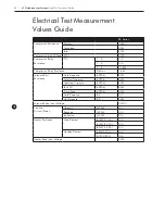
Page 46: ...sistance Klickson 1 6Ω Solenoid Coil Resistance Cold Dispense 0906 84Ω Ambient Dispense 0906 84Ω Sparkling Dispense 0906 84Ω Tank Fill 0906 84Ω Pump Feed 0906 84Ω Cold Dispense All N A Hot Dispense All 84Ω Solenoid Valve Input Voltage 24VDC Cooling Current Power Normal At 230V N A Reduced At 230V N A Ineffective At 230V N A Heater Resistance Main Element 400W 1 74A N A 535W 2 33A N A 825W 3 58A N ...

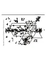
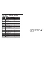
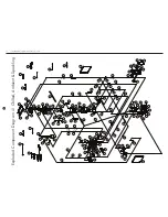
Page 47: ...P6 P5 P4 P14 P3 M20 M20 C23 C19 C18 C15 C14 C13 C12 C6 C3 C2 C1 M13 M12 E11 E6 E3 E7 E8 E8 E8 M11 M10 M9 M8 M8 M7 M6 M4 M3 M2 M1 P2 P1 M20 M21 M21 M21 M15 M15 M22 M19 M20 M16 M17 M21 M18 O3 M5 M19 E5 E4 M19 C34 C24 C14 C26 C14 C27 C31 C30 C29 C28 P15 GREEN YELLOW E10 紫 綠 藍 灰 白 白 灰 藍 綠 紫 棕 紫 黑 白 藍 白 棕 紫 藍 黑 黑 黃 黃 白 白 黃 藍 紅 黃 藍 紅 白 黑 白 黑 棕 白 黃 藍 黃 藍 黃 藍 黃 棕 棕 黃 黃 棕 黃 棕 棕 棕 白 藍 藍 藍 黃 棕 黃 Exploded Com...

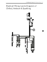
Page 48: ...48 u1 Undercounter Systems Install Operation Guide Electrical Wiring Loom Diagram u1 Chilled Ambient Exploded Component Diagram u1 Chilled Ambient E9 ...

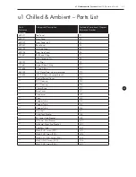
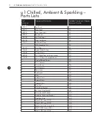
Page 49: ...21 Grit Filter P9 131661 Spigot Elbow Fitting P10 131648 Y Type Fitting P11 462003 1 4 Water Pipe white per metre P12 131655 1 4 T Fitting with spigot branch P13 Control Board Cover P14 PVC Sleeving P15 PVC Sleeving P16 10mm Bung P17 Rear Cover M1 Condenser M2 Drier M3 Copper Tube M4 Copper Tube M5 Copper Tube M6 Mid Shelf M7 Cold Tank Bracket M8 RH Lower Side Bracket M9 LH Lower Side Bracket M10 ...

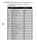
Page 50: ... 172163 IEC Fused Socket E5 173267 Cold Thermostat E6 174352 Fan E7 173241 Solenoid Valve E8 172173 Main Wiring Harness E9 Earth Wire Harness E10 172152 IEC Power Cordset UK E11 172148 IEC Power Cordset Shucko EURO E11 852108 IEC Power Cordset Swiss E11 172144 IEC Power Cordset Danish E11 Level Control Wiring Harness E12 Faucet Wiring Harness E13 172179 Swan Neck Faucet Connection Harness E14 Adap...

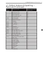
Page 51: ...ch C18 462003 1 4 Water Pipe white per metre C19 Hose Spring Clamp C20 Silicone Drain Pipe C21 Angled Bulkhead Fitting Back Nut C22 Foam Rubber Insert C23 131642 PF Inlet Elbow C24 DC Coil C25 131647 PF Elbow C26 1 4 DC Coil Nylon Connection Tube C27 Cold Tank Lid Bung C28 Level Sensor Probe C29 Angled Circulation Pump Tube C30 175363 DC Circulation Pump Set C31 Double Sided Fixing Pad C32 131643 ...

Page 52: ...P12 P12 E8 E8 P12 M9 M10 C33 C33 C25 C34 C33 C32 C28 C7 C29 C4 C10 C31 C11 C11 C30 C27 C24 P8 P7 P7 O1 C16 C17 C20 C21 E15 E14 E13 E12 E9 E1 M14 P8 P7 P7 P7 P6 P5 P4 P3 C23 C19 C18 C15 C11 C13 C12 C6 C3 C2 C1 M13 M12 E11 E6 E3 E7 M8 M8 M7 M6 M4 M3 M2 M1 P2 P1 M20 M21 M21 M21 M15 M15 M22 M19 M20 M16 M17 M21 M18 O2 M5 M19 E5 E4 M19 GREEN YELLOW E10 紫 綠 藍 灰 白 白 灰 藍 綠 紫 棕 紫 黑 白 藍 白 棕 紫 藍 黑 白 白 黃 黃 白 黃...

Page 53: ...GB u1 Undercounter Systems Install Operation Guide 53 Electrical Wiring Looms Diagram u1 Chilled Ambient Sparkling E9 ...

Page 54: ... 194121 Grit Filter P9 131661 Spigot Elbow Fitting P10 131648 Y Type Fitting P11 462003 1 4 Water Pipe white per metre P12 131653 1 4 T Fitting with spigot branch P13 Control Board Cover P14 PVC Sleeving P15 10mm Bung P16 PVC Sleeving P17 Rear Cover M1 Condenser M2 Drier M3 Copper Tube M4 Copper Tube M5 Copper Tube M6 Mid Shelf M7 Cold Tank Bracket M8 RH Lower Side Bracket M9 LH Lower Side Bracket...

Page 55: ...Off Switch E4 172163 IEC Fused Socket E5 173267 Cold Thermostat E6 174352 Fan E7 173241 Solenoid Valve E8 172173 Main Wiring Harness E9 Earth Wire Harness E10 172152 IEC Power Cordset UK E11 172148 IEC Power Cordset Shucko EURO E11 852108 IEC Power Cordset Swiss E11 172144 IEC Power Cordset Danish E11 Level Control Wiring Harness E12 Faucet Wiring Harness E13 172179 Swan Neck Faucet Connection Har...

Page 56: ...ulation Pump Set C24 Angled Circulation Pump Tube C25 M5x12 RHD Screw 200 C26 1 4 DC Coil Nylon Connection Tube C27 Cold Tank Lid Bung C28 Level Sensor Probe C29 Circulation Pump Tube Clip C30 M4x16 St St PHD Screw 200 C31 Carbonation Tank Set Complete C32 131643 1 4 Stem Elbow C33 132448 SCV 1 Way Valve C34 Elbow Vent Fitting C35 EPS Filler Block C36 EVA Foam Soft C37 174378 Carbonation Pump Set ...

Page 57: ...rcuit Diagram u1 Chilled Ambient 58 Electrical Circuit Diagram u1 Chilled Ambient Sparkling 59 Water Pathway Diagram u1 Chilled Ambient 60 Water Pathway Diagram u1 Chilled Ambient Sparkling 62 Certificate Electrical Circuit Water Pathway Diagrams u1 Undercounter Systems All Models ...

Page 58: ...ff Switch DC Tank Pump Detection Probe Fan Red Blue Yellow Orange Purple White Ambient Dispense Solenoid Compressor Cold Dispense Solenoid Fill Solenoid Thermostat DANGER HIGH VOLTAGE 24V DC Transformer Direct Chill Tank DANGER HIGH VOLTAGE Live DANGER HIGH VOLTAGE 230 AC Inlet Neutral Main Control Board ...

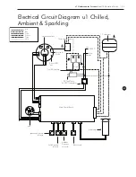
Page 59: ...ion Probe Fan Red Blue Yellow Orange Purple White Ambient Dispense Solenoid Compressor Sparkling Dispense Solenoid Soda Pump Thermostat 24V DC Transformer Direct Chill Tank DANGER HIGH VOLTAGE Live 230 AC Inlet Neutral Main Control Board Carbonation Tank DANGER HIGH VOLTAGE DANGER HIGH VOLTAGE DANGER HIGH VOLTAGE Fill Solenoid Cold Dispense Solenoid ...

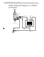
Page 60: ...Systems Install Operation Guide GB Water Pathway Diagram u1 Chilled Ambient Direct Chill Coil Faucet Cold Solenoid Valve Direct Chill Tank Fill Solenoid Ambient Solenoid Valve Direct Chill Tank Water Inlet Drainage Outlet ...

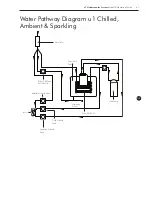
Page 61: ...Guide 61 GB Water Pathway Diagram u1 Chilled Ambient Sparkling Faucet Cold Solenoid Valve Soda Pump Direct Chill Coil Direct Chill Tank Ambient Solenoid Valve Water Inlet Direct Chill Tank Fill Solenoid Drainage Outlet Sparkling Solenoid Valve ...

Page 62: ...62 u1 Undercounter Systems Install Operation Guide GB ...

Page 63: ...u1 Undercounter Systems Install Operation Guide 63 GB ...

Page 64: ...ion Operation u1 Chilled Ambient Sparkling 22 Major Components 27 Water Connection 28 CO2 Bottle Installation Sparkling Water Operation 33 Sanitisation Guides 37 Trouble Shooting 45 Electrical Measurements Component Diagrams Lists 56 Electrical Circuit Water Pathway Diagrams 62 Certificat Telephone 44 0 1362 695 006 Email sales borgandoverstrom com borgandoverstrom com Synergy House Fakenham Road ...

Reviews: