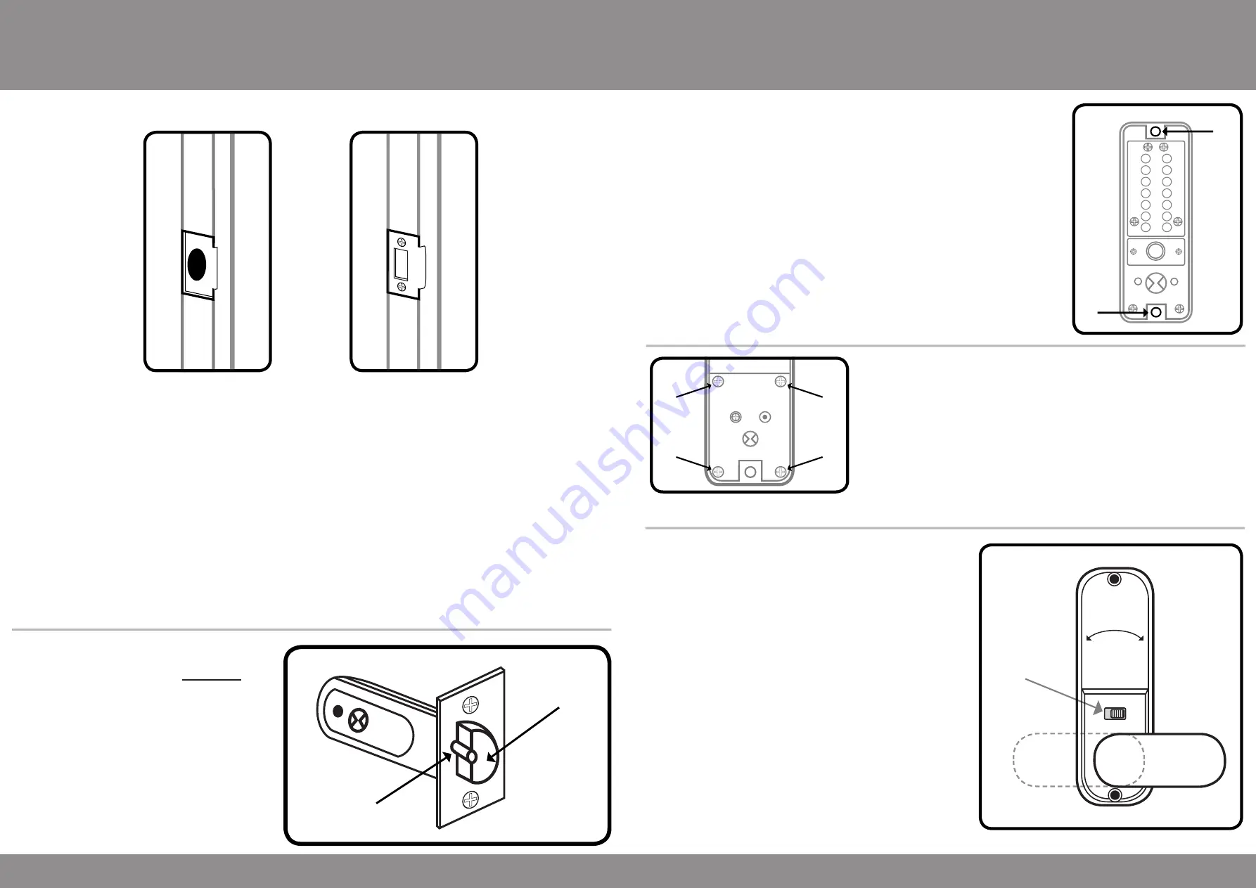
Fitting the Hexagonal Support Posts
Fit both of the hexagonal support posts
(part no.9)
into the top and bottom
threaded holes of the keypad, as shown in the diagram.
Do not over tighten the hexagonal support posts as this may strip the
thread on either the post itself or the thread in the back of the keypad.
1
2
3
4
5
X
Y
6
7
8
9
0
Z
C
A
B
V3
3
Removing the Holdback Function
If you do not require the holdback function on the inside handle
(holback
models model only)
this feature can be removed.
On the back of the inside handle
(part no. 2)
, unscrew all of the screws as
shown on points
A
,
B
,
C
and
D
on the diagram.
With the 4 screws removed the plate can now be lifted out of position, this
will reveal the holdback snib, which has a spring and ball bearing attached.
Remove the holdback snib, spring and ball bearing and place the hold back
snib blank
(part no. 7)
in the hole.
A
B
C
D
V3
Preparation
Installation
6
Fitting the Strike Plate & Box Keep
Anti-Thrust Pin
Latchbolt
Push the door to the closed position and mark the area on the frame of the door where the strike plate would need
to be fitted.
Open the door and now mark the innner and outer edges of the strike plate. Using a sharp chisel remove 1mm of
material from the frame of the door
until the strike plate can sit flush.
With the material for the strike plate removed from the frame of the door, the material for the box keep will need to
be removed. Place the box keep in the cut-out made for the strike plate and draw around the box keep. You will
need to remove 36mm high, 23mm wide and 13mm deep of material to accommodate the box keep, alternatively a
20mm diameter by 15mm deep hole can be drilled in the frame to allow the latchbolt to fully protrude when the door
is in its closed position.
To secure the strike plate and box keep in place use two of the wood screws
(part no. 14)
. Now that the strike and
the box keep have been secured in place the door can be closed. Ensure that the keypad and inside handle with-
draw the latch when the door is in its closed position.
If the operation of the lock is excessively stiff when turning the keypad or inside handle, the strike plate
and box keep position will need to be adjusted.
Please note the anti-thrust beside the latchbolt (as
per the diagram), this deadlocks the latchbolt and
protects it against manipulation.
It must not
enter
the hole made for the latchbolt when the door is
closed.
If the anti-thrust pin does go into hole for the
latchbolt, adjust the position of the strike plate
until the anti-thrust pin sits on the face of the
strike plate.
Operating the Holdback Function
To operate the holdback function the handle will need be
turned a full 90° to the left or right (depending on the handing
of the door.
If the unit is fitted to a left hand hung door the handle will need
to be turned to the right (clockwise) and the snib will need to
be pushed to the left. When the snib has been pushed across
the handle will stay in the rotated position and the latchbolt in
the edge of the door will be withdrawn.
If the unit is fitted to a right hand hung door the handle will
need to be turned to the left (anti-clockwise) and the snib
will need to be pushed to the right. When the snib has been
pushed across the handle will stay in the rotated position and
the latchbolt in the edge of the door will be withdrawn.
To release the holdback function a small amount of pressure
will need to be applied to the handle to allow you to push
the snib across. With the snib pushed across the handle will
spring back to its vertical position and the latchbolt in the edge
door will now be visible.
Holdback
Snib


