4
V3
Drilling the Door & Fixing the Latch
With all the drilling points marked out on the door, the holes can be drilled.
All of the 6 x 8mm holes will need to be drilled through the door. The remaining material which will be around the 4 x
8mm horizontal holes will need to be removed with a sharp chisel.
Where the ‘centre line of latch’ is marked on the template, drill a 25mm wide and 85mm deep hole in the edge of the
door to accommodate the barrel of the latch.
Insert the barrel of the latch into the hole in the edge of the door and draw around the rectangular face plate latch.
With the face plate marked, remove the latch from the hole in the door. Now remove 3mm of material from the door
so that the face plate of the latch sits flush with the door edge. With the latch positioned in the door it can now be
secured using two of the woods screws
(part no. 14)
via the two screw holes in the face plate of the latch.
Apply the Drilling Template
Tape the template to the door and ensure that the dotted line on the template is
aligned to the edge of the door.
Mark all six of the 8mm holes as shown on the drilling template.
Mark on the door ‘centre line of latch’ ensuring that the centre line for the latch is in
the centre on the edge of the door.
Installation
Fitting & Positioning the Spindle
Select one of the two spindles
(part no.10 - 100mm spindle)
or
(part no. 11 - 85mm spindle)
supplied in the accessory pack. Use
the longest spindle possible. Cutting the spindle down may be re-
quired, but this would depend entirely on the thickness of the door.
Please note if the spindle is cut too short this may cause the
spindle to slip out of position if the door is slammed and re-
sult in users being locked out.
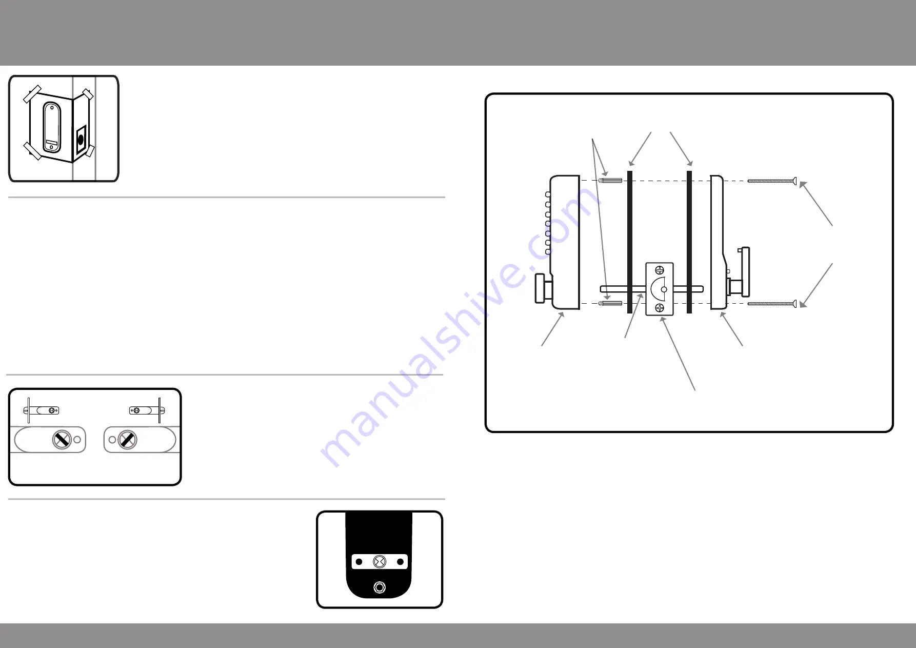
Fitting the Keypad & Inside Handle
Place one of the rubber gaskets (part no.3) around the back of the keypad,
ensuring that the gasket is the correct way up and that the spindle follower is
still visible. As per the image.
The fixing posts at the top and bottom on the reverse of the keypad will sit in
the very top and bottom 8mm holes drilled in the face of the door. When in
place ensure that the spindle is located into the spindle follower on back of the
keypad.
Continued of page no.5.
5
V3
Place the remaining rubber gasket
(part no. 3)
around the back of the inside handle and as with the keypad side
the spindle follower on the back of the inside handle will need to be visible.
With the keypad in place on the door and the inside handle having the rubber gasket in place the inside handle
can be offered up to the door and secured in place using one pair of the machine screws
(part no. 12 or 13)
. The
length of machine screw used would depend entirely on the thickness of the door.
Once the unit has been secured onto the door the unit can be tested on the set code. Check that both the keypad
and inside handle retract the latch fully.
Please note if the latch does not retract, the spindle has been put in the incorrect way. Please refer to ‘fitting and
positioning the spindle’ on
(page no.4)
as how to insert the spindle into the latch.
If the spindle is too short for the thickness of door, you will find that you will only be able to retract the latch from
one side of the door and therefore you will need to remove and replace with a longer spindle.
If you find the operation of the unit is very stiff when you are testing, either the unit has been over tightened on the
door and would need to be loosened or not enough material has been removed when drilling out the hole for the
barrell of the latch and therefore the unit will need to be taken off of the door and more material removed
.
Installation
Gaskets
(part no.3)
Keypad
(part no.1)
Inside Handle
(part no.2)
Machine Screws
(part no.12/13)
Hexagon Support
Posts
(part no.9)
Spindle
(part no.10/11)
Tubular Latch
(part no.4)
Secured in place with 2 wood screws
(part no.14)
Fitting Illustration
Right Hand
Left Hand
As viewed from the outside
of the door


