background image

Installation 

Fitting & Positioning the Spindle

Tubular Latch/lock case - non key override models 

Select one of the two spindles supplied 80mm/90mm - use the longest spindle possible. Trimming the spindle down 

may be required, but this would depend entirely on the thickness of the door. It is recommended that 15mm of the 

bladed part of the spindle goes into the back of the keypad and inside handle e.g. If the door is 44mm thick the over-

all spindle length wants to be 74mm.  

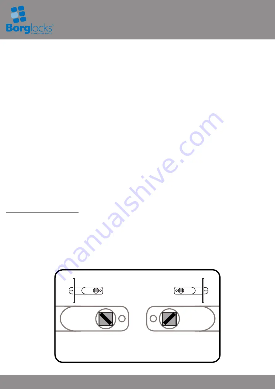
When putting the spindle through the latch/lock case, ensure that the bladed part of the spindle is angled to the top 

opening edge of the door as per image


below. 

Please note if the spindle is cut too short this may cause the spindle to slip out of position if the door is 

slammed and result in users being locked out. 

Tubular Latch/Lock case - Key Override Models


The unit is supplied with a sprung spindle. The spindle comes preset to suit a right hand hung door; whereby the 

spring is located around the bladed part of the spindle which will go into the inside handle. The spring is fitted to the 

spindle to ensure the spindle is located and held into the back of the keypad to allow the key override to function 

correctly. Once you have determined what side of the spindle will go into the inside handle - if the spindle needs to 

be trimmed it is recommended that the blade which will be going into the back of the inside handle is trimmed.

When putting the spindle through the latch/lock case, ensure that the bladed part of the spindle is angled to the top 

opening edge of the door as pe

r image below. 

Please note if the spindle is cut too short on the side which goes into the keypad the key override

will not work; however the inside handle and keypad will operate correctly after entering the correct code. 

Narrow Stile/Aluminium Latch

Select one of the three spindles supplied 80mm/90mm or 130mm


- use the longest spindle possible. Trimming the 

spindle down may be required, but this would depend entirely on the thickness of the door. It is recommended that 

15mm of the bladed part of the spindle goes into the back of the keypad and inside handle e.g. If the door is 54mm 

thick the overall spindle length wants to be 84mm.  

When putting the spindle through the latch/lock case, ensure that the bladed part of the spindle is angled to the top 

opening edge of the door as pe

r image below. 

Right Hand


Left Hand


As viewed from the outside of the 

door when fitting with tubular latch 

3

BL5000 ECP Models 

Summary of Contents for BL5000 ECP

Page 1: ...removing the grey grommet located on the side of the keypad handle this will expose the head of the grub screw underneath Using the hex wrench remove the grub screw and this will allow the handle to come away from the handle holder Place the handle onto the handle holder facing in the correct direction for your hand of door The grub screw can be tightened back in and the grommet can be replaced BL...

Page 2: ...the door and the free passage deactivation plug removed Deactivating on the Door Code Change In the event where it is known the code will never need to be changed on the door the deactivating on door code change plug from the accessory pack can be fitted prior to the unit being fitted to the door On the back of the keypad you will see a hole with a indicating arrow in the top centre Using the on d...

Page 3: ... the keypad to allow the key override to function correctly Once you have determined what side of the spindle will go into the inside handle if the spindle needs to be trimmed it is recommended that the blade which will be going into the back of the inside handle is trimmed When putting the spindle through the latch lock case ensure that the bladed part of the spindle is angled to the top opening ...

Page 4: ...ntering a new code with the ɸ button rotated and pressed the C clear button can be pressed which will cancel any buttons that have been pressed and you can start again 5 With the new code entered the code change key can be removed by releasing the pressure and rotating 90 left clockwise and remove the key from the ɸ button 6 Press C button turn the keypad handle to set the new code 7 The new code ...

Page 5: ... handle or knob handle can be released and the unit will reset The door can be closed and the unit will be locked from the keypad side Operating with the Key Override The following instructions are only applicable for the BL5700 BL5701 BL5702 or BL5703 models with built in key override Please note the BL5703 model only operates the latchbolt of the lock case If the deadbolt is thrown using the sep...

Page 6: ... closest to the centre of the portholes 4 As per the example diagram below you will see that the red lines on digits 2 4 6 and 8 are closest to the centre of the porthole and is therefore the code All the other holes will show a blue line these are not in the code Once all the coded buttons have been pressed all of the 10 holes will have a blue lines in the centre of the portholes 5 There is no se...

Reviews: