6
www.BormannTools.com
32.
WARNING:
Handling the cord on this product will expose you to lead, a chemical known to the State of California to cause
cancer, and birth defects or other reproductive harm. Wash hands after handling. (California Health & Safety Code § 25249.5,
et
seq.
)
SAVE THESE INSTRUCTIONS!
Grounding
TO PREVENT ELECTRIC SHOCK AND DEATH FROM INCORRECT GROUNDING WIRE CONNECTION: Check with a
qualified electrician if you are in doubt as to whether the outlet is properly grounded. Do not modify the power
cord plug provided with the s prayer. Never remove the grounding prong from the p lug. Do not use the sprayer if
the power cord or plug is damaged. If damaged, have it repaired by a service facility before use. If the plug will not
fit the outlet, have a proper outlet installed by a qualified electrician.
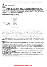
Grounded Sprayers: Sprayers with Three Prong Plugs
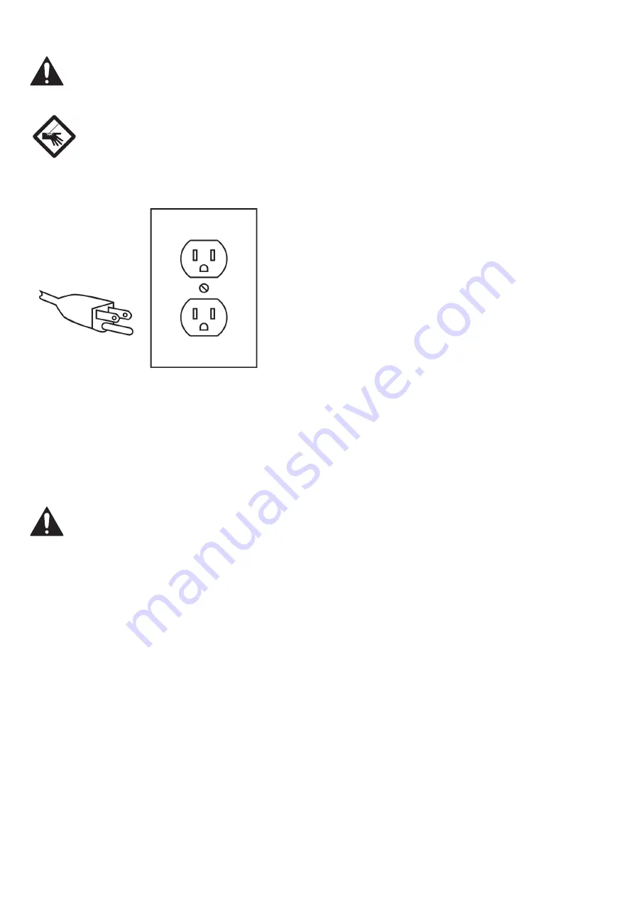
3 -Prong Plug and Outlet
1. Sprayers marked with “Grounding required” have a three wire cord and three prong grounding plug. The plug must be
connected to a properly grounded outlet. If the sprayer should electrically malfunction or break down, grounding provides a low
resistance path to carry electricity away from the user, reducing the risk of electric shock.
(See 3-Prong Plug and Outlet.)
2. The grounding prong in the plug is connected through the green wire inside the cord to the grounding system in the sprayer.
The green wire in the cord must be the only wire connected to the sprayer’s grounding system and must never be attached to an
electrically “live” terminal.
(See 3-Prong Plug and Outlet.)
3. The sprayer must be plugged into an appropriate outlet, properly installed and grounded in accordance with all codes and
ordinances. The plug and outlet should look like those in the preceding illustration.
(See 3-Prong Plug and Outlet.)
CAUTION! All electrical equipment connections including the socket and cables of the machine should only be made by
a professional electrician or by a specialist manufacturer of the Service department of the manufacturer, respectively!
Extension Cords
1.
Grounded
sprayers require a three wire extension cord.
Double Insulated
sprayers can use either a two or three wire extension
cord.
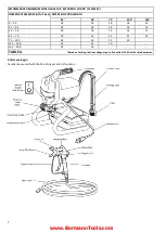
2. As the distance from the supply outlet increases, you must use a heavier gauge extension cord. Using extension cords with
inadequately sized wire causes a serious drop in voltage, resulting in loss of power and possible sprayer damage.
(See Table A.)
3. The smaller the gauge number of the wire, the greater the capacity of the cord. For example, a 14 gauge cord can carry a higher
current than a 16 gauge cord.
(See Table A.)
4. When using more than one extension cord to make up the total length, make sure each cord contains at least the minimum wire
size required.
(See Table A.)
5. If you are using one extension cord for more than one sprayer, add the nameplate amperes and use the sum to determine the
required minimum cord size.
(See Table A.)
6. If you are using an extension cord outdoors, make sure it is marked with the suffix “W-A” (“W” in Canada) to indicate it is
acceptable for outdoor use.
7. Make sure the extension cord is properly wired and in good electrical condition. Always replace a damaged extension cord or
have it repaired by a qualified electrician before using it.
8. Protect the extension cords from sharp objects,
excessive heat, and damp or wet areas.
Summary of Contents for 022930
Page 1: ...BAP6500 Owner s manual Art Nr 022930 www BormannTools com...
Page 2: ...2 www BormannTools com GR Service...
Page 4: ...4 www BormannTools com 1 2 GFCI GFCI 3 ANSI NIOSH 4...
Page 6: ...6 www BormannTools com 27 28 29 30 31 25249 5 32 25249 5 Service 1 3 2 3 3 Service...
Page 8: ...8 www BormannTools com ON OFF...
Page 9: ...9 www BormannTools com Service Eject...
Page 10: ...10 www BormannTools com 1 2 3...
Page 11: ...11 www BormannTools com OFF 1 OFF 2 Prime 3 4 Prime...
Page 12: ...12 www BormannTools com 1 2 3 4 Prime 5 ON 6 OFF 7 30 60 Off 8 ON 9...
Page 13: ...13 www BormannTools com 10 11 Spray 12 13 14 15...
Page 14: ...14 www BormannTools com 30 cm 1 2 1 30 cm 2 3...
Page 15: ...15 www BormannTools com OFF 1 OFF 2 CLEAN 3 Spray ON 4 O 5 6 7 8 9 10 11 OFF 12 13 14...
Page 16: ...16 www BormannTools com 48 15 16 1 2 3 30ml 4 SPRAY 5 6 ON 5 seconds then OFF 7 5 OFF 8 9 10...
Page 18: ...18 www BormannTools com Service...


