background image

www.BormannTools.com 

Καλώδια προέκτασης


1. Τα γειωμένα μηχανήματα


απαιτούν καλώδιο προέκτασης τριών


αγωγών. Τα διπλά μηχανήματα


μπορούν να χρησιμοποιήσουν 

ένα καλώδιο προέκτασης δύο ή τριών αγωγών.


2. Καθώς αυξάνεται η απόσταση από την πρίζα, πρέπει να χρησιμοποιήσετε καλώδιο προέκτασης μεγαλύτερου


διαμετρήματος. 

Η χρήση καλωδίων προέκτασης με αγωγό


ανεπαρκούς διαμέτρου


προκαλεί σοβαρή πτώση της τάσης, με αποτέλεσμα απώλεια 

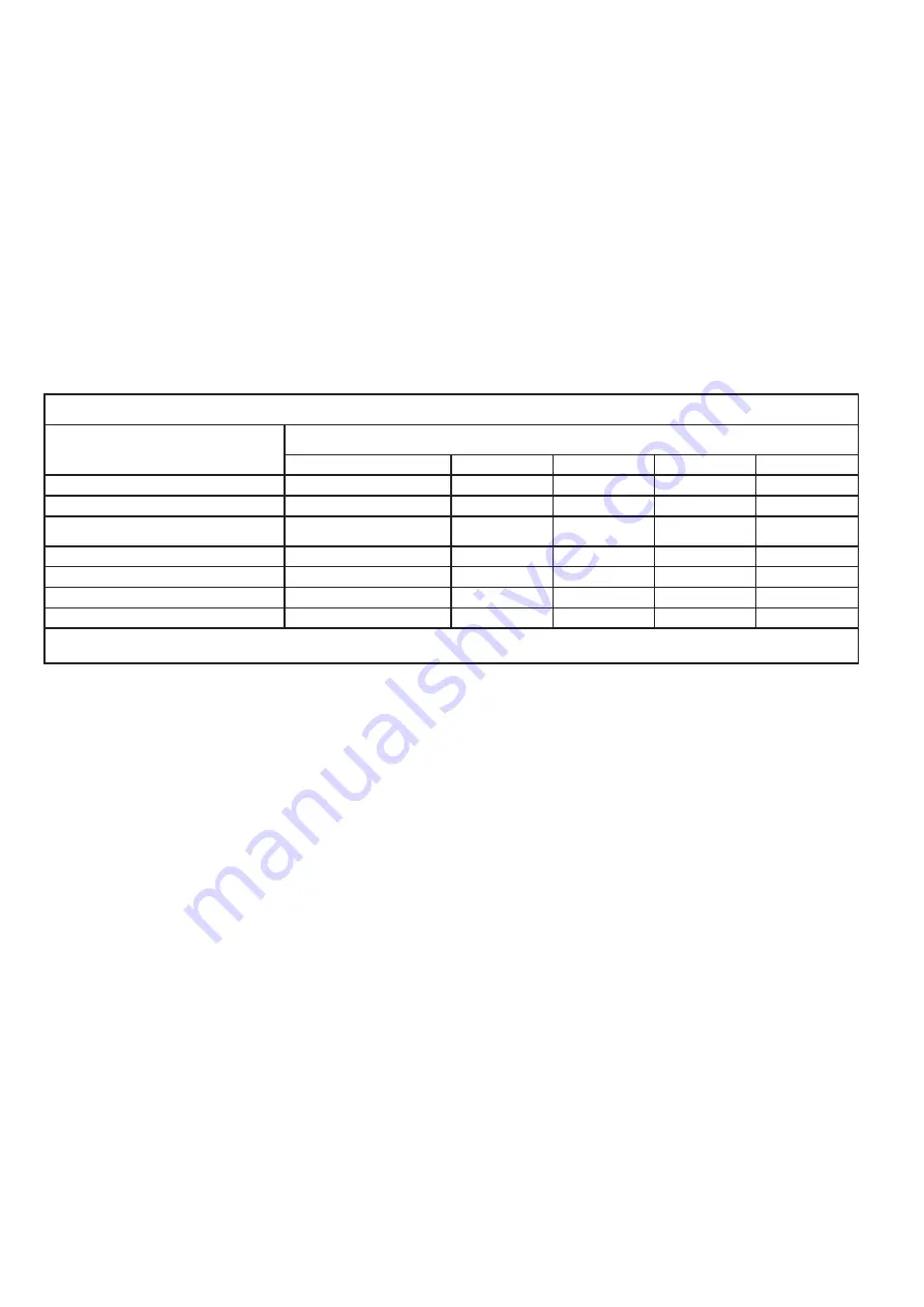
ισχύος και πιθανή ζημιά στο μηχάνημα. (Βλ. Πίνακα Α).


3. Όσο μικρότερη


είναι


η


διάμετρος


του καλωδίου, τόσο μεγαλύτερη είναι η χωρητικότητα του καλωδίου. Για παράδειγμα, ένα 

καλώδιο μήκους 14 μπορεί να φέρει υψηλότερο ρεύμα από ένα καλώδιο 16 διαμετρήματος. (Βλ. Πίνακα Α).


4. Όταν χρησιμοποιείτε περισσότερα από ένα καλώδια προέκτασης για να συμπληρώσετε το συνολικό μήκος, βεβαιωθείτε ότι 

κάθε καλώδιο περιέχει τουλάχιστον τα κατάλληλα χαρακτηριστικά. (Βλ. Πίνακα Α).


5. Εάν χρησιμοποιείτε ένα καλώδιο προέκτασης για περισσότερα από ένα μηχανήματα προσθέστε τις πλάκες πινακίδας και 

χρησιμοποιήστε το άθροισμα για να καθορίσετε το απαιτούμενο ελάχιστο μέγεθος καλωδίου. (Βλ. Πίνακα Α).


6. Εάν χρησιμοποιείτε εξωτερικό καλώδιο προέκτασης, βεβαιωθείτε ότι έχει επισημανθεί με το επίθεμα "

W-A

" ("

W

" στον 

Καναδά) για να βεβαιωθείτε ότι είναι κατάλληλο για εξωτερική χρήση.


7. Βεβαιωθείτε ότι το καλώδιο προέκτασης είναι καλώς συνδεδεμένο και βρίσκεται σε καλή λειτουργική


κατάσταση. Να 

αντικαθιστάτε πάντα ένα κατεστραμμένο καλώδιο προέκτασης ή να το επισκευάσετε παραδίδοντάς το σε έναν ειδικευμένο 

ηλεκτρολόγο πριν το χρησιμοποιήσετε.


8. Προστατέψτε τα καλώδια προέκτασης


από αιχμηρά αντικείμενα, υπερβολική θερμότητα και την υγρασία.


Προτεινόμενη διάμετρος καλωδίων προέκτασης

* (120/240 V) 

Ονομαστικά Αμπέρ

 (

Σε πλήρη 

φορτίο


Μήκος καλωδίου προέκτασης


25’ 

50’ 

75’ 

100’ 

150’ 

 0 – 

2.0


18 

18 

18 

18 

16 


2.1 

– 

3.4


18 

18 

18 

16 

14 


3.5 

– 

5.0


18 

18 

16 

14 

12 


5.1 

– 

7.0


18 

16 

14 

12 

12 


7.1 

– 

12.0


18 

14 

12 

10 


12.1 

– 

16.0


14 

12 

10 


16.1 

– 

20.0


12 

10 


Πίνακας

 A                     

* Με βάση τον περιορισμό της πτώσης


τάσης γραμμής στα 5 βολτ στο 150% των ονομαστικών αμπέρ.


Summary of Contents for 022930

Page 1: ...BAP6500 Owner s manual Art Nr 022930 www BormannTools com...

Page 2: ...2 www BormannTools com GR Service...

Page 3: ...3 www BormannTools com PSI NPT NPS ANSI NIOSH 220v 50hz 650w 4 7 5a 2 4 5a 210bar 1100ml min 517 size 311 300mm Fan pattern width 250 310mm...

Page 4: ...4 www BormannTools com 1 2 GFCI GFCI 3 ANSI NIOSH 4...

Page 5: ...5 www BormannTools com 5 Service Service 1 2 3 4 5 6 7 8 9 10 11 12 13 14 15 21 C MSDS 16 17 18 19 3000 PSI 20 21 22 23 24 25 26...

Page 6: ...6 www BormannTools com 27 28 29 30 31 25249 5 32 25249 5 Service 1 3 2 3 3 Service...

Page 7: ...ls com 1 2 3 14 16 4 5 6 W A W 7 8 120 240 V 25 50 75 100 150 0 2 0 18 18 18 18 16 2 1 3 4 18 18 18 16 14 3 5 5 0 18 18 16 14 12 5 1 7 0 18 16 14 12 12 7 1 12 0 18 14 12 10 12 1 16 0 14 12 10 16 1 20...

Page 8: ...8 www BormannTools com ON OFF...

Page 9: ...9 www BormannTools com Service Eject...

Page 10: ...10 www BormannTools com 1 2 3...

Page 11: ...11 www BormannTools com OFF 1 OFF 2 Prime 3 4 Prime...

Page 12: ...12 www BormannTools com 1 2 3 4 Prime 5 ON 6 OFF 7 30 60 Off 8 ON 9...

Page 13: ...13 www BormannTools com 10 11 Spray 12 13 14 15...

Page 14: ...14 www BormannTools com 30 cm 1 2 1 30 cm 2 3...

Page 15: ...15 www BormannTools com OFF 1 OFF 2 CLEAN 3 Spray ON 4 O 5 6 7 8 9 10 11 OFF 12 13 14...

Page 16: ...16 www BormannTools com 48 15 16 1 2 3 30ml 4 SPRAY 5 6 ON 5 seconds then OFF 7 5 OFF 8 9 10...

Page 17: ...17 www BormannTools com 1 2 1 2 1 2 3 1 2 3 1 2 3 4 5 1 2 3 4 5 1 2 3 1 2 3 1 2 3 1 2 3 1 2 3 1 2 3...

Page 18: ...18 www BormannTools com Service...

Page 19: ...ractices not related to personal injury CAUTION without the safety alert symbol is used to address practices not related to personal injury WARNING Read all instructions Failure to follow all instruct...

Page 20: ...ing concerning Risk of Respiratory Injury Wear NIOSH approved respirator WARNING marking concerning Risk of Explosion WARNING marking concerning Risk of Injection Injury Do not direct spray at hands o...

Page 21: ...ns b Dress properly Do not wear loose clothing or jewelry Contain long hair Keep hair clothing and gloves away from moving parts Loose clothes jewelry or long hair increases the risk of injury to pers...

Page 22: ...amine hoses regularly and replace if damaged 18 When flushing Paint Sprayer system use lowest possible pressure setting 19 All hoses and spray gun accessories used with Paint Sprayer must be pressure...

Page 23: ...rayer must be plugged into an appropriate outlet properly installed and grounded in accordance with all codes and ordinances The plug and outlet should look like those in the preceding illustration Se...

Page 24: ...OR EXTENSION CORDS 120 240 V NAMEPLATE AMPERES At full load EXTENSION CORD LENGTH 25 50 75 100 150 0 2 0 18 18 18 18 16 2 1 3 4 18 18 18 16 14 3 5 5 0 18 18 16 14 12 5 1 7 0 18 16 14 12 12 7 1 12 0 18...

Page 25: ...t and the warranty validity all repair inspection repair or replacement work including maintenance and special adjustments must only be carried out by technicians of the authorized service department...

Page 26: ...rotect from overspray paint mist Hi pressure spray Prime Clean Low pressure spray Rolling 1 Attach Paint Hose to Paint Hose Outlet and tighten with wrench 2 Attach Paint Hose to Paint Gun and tighten...

Page 27: ...Turn Power Switch off and unplug unit from outlet 2 Switch Prime Spray switch to Prime mode 3 Point gun into paint pail and activate Sprayer Trigger to relieve pressure 4 Turn Trigger Lock Knob to lo...

Page 28: ...g solvent 4 Turn Prime Spray switch to Prime mode Hi Spray Low Spray Prime clean Roll 5 Adjust Pressure Control Knob to Prime Clean setting ON 6 Plug in Sprayer and turn on power OFF 7 Sprayer will st...

Page 29: ...e 13 Remove the Priming Tube from the waste bucket and clip to Suction Tube and submerge in paint pail 14 If the motor stops the pump and tubes are primed If it does not stop repeat priming steps 15 S...

Page 30: ...clean setting 3 Turn Spray Prime Switch to spray mode ON 4 Switch Power to On 5 Unlock Trigger 6 Spray into waste bucket until clog clears 7 Release Trigger and engage Trigger Lock 8 Adjust nozzle to...

Page 31: ...nt hose if not already removed 2 Turn the unit over and loosen the Clamps from both Tubes then disconnect Tubes from the Pump Body 3 Add one ounce of light household oil or a pump storage product into...

Page 32: ...drier 2 Start each stroke off the work material and overlap each stroke consistently 3 Use a conditioner or sealer coat before applying the finish coat Spots on surface with light center fish eyes 1 P...

Page 33: ...16 www BormannTools com Assembly Diagram...

Page 34: ...utput Gear Washer 1 26 Gear 1 27 Gear Bushing 6 35 2 28 Gear Washer 1 29 Middle Gear Bushing 1 30 Label 1 31 Pressure Knob 1 32 Label 1 33 Pressure Control Bolt M4x8 1 34 Spring Pusher A 1 35 Pressure...

Page 35: ...g 17x1 8 1 79 Paint input Adaptor 1 80 Clamp 16 25 2 81 Clamp 10 5 1 82 Priming Tube 1 83 Suction Tube 1 84 Clip 3 85 Filtrate Seat Assembly 1 86 Pin 5 10 2 87 Hex Bolt M5 15 4 88 Elastic Washer 5 4 8...

Reviews: