EN
WWW.BORMANNTOOLS.COM
4
Safety instructions
To avoid possible electric shock or personal injury, and to avoid possible damage to the Meter or to the equipment under test, adhere to the following rules:
1. Before using the Meter inspect the case. Do not use the Meter if it is damaged or the case (or part of the case) is removed. Look for cracks or missing
plastic. Pay attention to the insulation around the connectors.
2. Inspect the test leads for damaged insulation or exposed metal. Check the test leads for continuity.
3. Do not apply more than the rated voltage, as marked on the Meter, between the terminals or between any terminal and grounding.
4. The rotary switch should be placed in the right position and no any changeover of range shall be made during measurement is conducted to prevent dam-
age of the Meter.
5. When the Meter working at an effective voltage over 60V in DC or 30V rms in AC, special care should be taken for there is danger of electric shock.
6. Use the proper terminals, function, and range for your measurements.
7. Do not use or store the Meter in an environment of high temperature, humidity, explosive, inflammable and strong magnetic field. The performance of the
Meter may deteriorate after dampened.
8. When using the test leads, keep your fingers behind the finger guards.
9. Disconnect circuit power and discharge all high-voltage capacitors before testing resistance, continuity, diodes or hFE.
10. Replace the battery as soon as the battery indicator appears. With a low battery, the Meter might produce false readings that can lead to electric shock
and personal injury.
11. Remove the connection between the testing leads and the circuit being tested, and turn the Meter power off before opening the Meter case.
12. When servicing the Meter, use only the same model number or identical electrical specifications replacement parts.
13. The internal circuit of the Meter shall not be altered at will to avoid damage of the Meter and any accident.
14. Soft cloth and mild detergent should be used to clean the surface of the Meter when servicing. No abrasive and solvent should be used to prevent the
surface of the Meter from corrosion, damage and accident.
15. The Meter is suitable for indoor use.
16. Turn the Meter power off when it is not in use and take out the battery when not using for a long time. Constantly check the battery as it may leak when
it has been using for some time, replace the battery as soon as leaking appears. A leaking battery will damage the Meter.
Overload Protection:
220V rms AC for 200mV range and 600V rms for all ranges.
Overload Protection:
500mA/250V fuse (10A range unfused).
MEASURING VOLTAGE DROP:
200mV
Overload Protection:
15 seconds maxi-mum 220 V rms.
Response:
Average responding, calibrated in rms of a sine wave.
Frequency Range:
45Hz ~ 450Hz OVERLOAD PROTECTION: 600 V rms for all ranges.
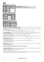
DC VOLTAGE
Range Resolution
Accuracy
200mV
100uV
±(0.5% of rdg + 3D)
2V
1mV
±(0.8% of rdg + 5D)
20V
10mV
200V
100mV
600V
1V
±(1.0% of rdg + 5D)
DC VOLTAGE
Range Resolution
Accuracy
200uA
100nA
±(1.8% of rdg +2D)
2mA
1uA
20mA
10uA
200mA
100uA
±(2.0% of rdg +2D)
10A
10mA
±(2.0% of rdg +10D)
AUDIBLE CONTINUITY
Range Description
Built-in buzzer sounds if resistance is
less then 30±20Ω
AC VOLTAGE
Range Resolution
Accuracy
200mV
100uV
±(2.0% of rdg +10D)
600V
1V


