background image

4 | 5

DRYPACK

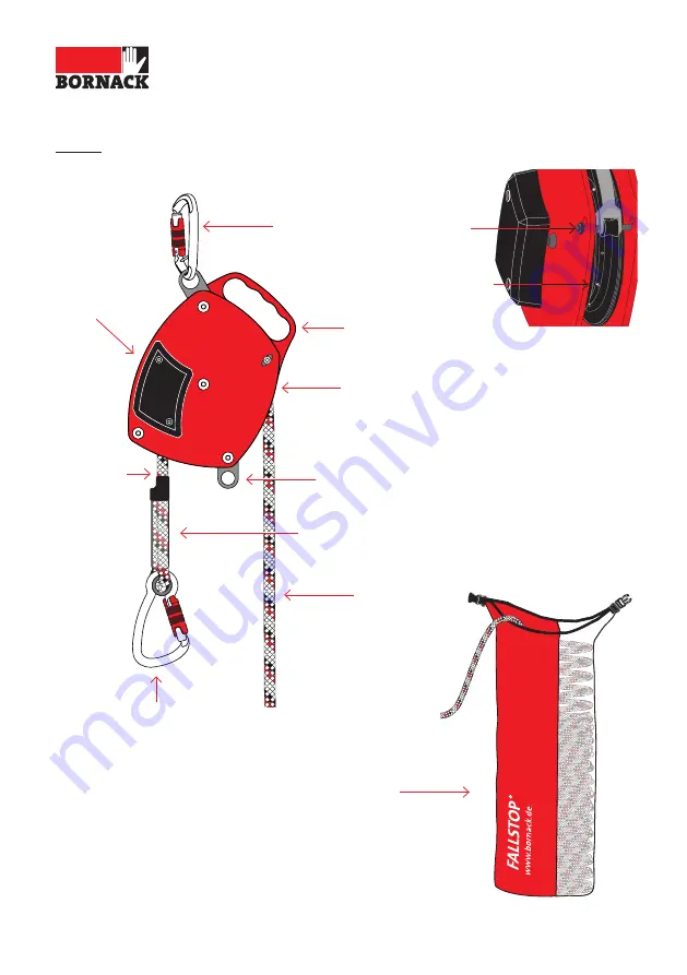
Connector acc. 

to EN 362

Pull rope

Strap for attaching 

the hoist

Carrying handle

Basic unit with 

identification

Thimble with 

identification

Connector acc. to 

EN 362, permanently 

attached to the  

basic unit

Supporting 

rope

LH200

Pin

Cover over the 

mechanical 

part

Lock  

washer

Summary of Contents for LH200

Page 1: ...Translation of the original instructions EN Directive 2006 42 EC on machinery LH200 ...

Page 2: ...epending on the ratio 1 1 without a hoist 25 kg 2 1 hoist 50 kg 3 1 hoist 75 kg 4 1 hoist 100 kg 5 1 hoist 125 kg Minimum weight of the load depending on the ratio see diagrams from page 18 Application temperature 30 C to 60 C All other uses are deemed improper The company BORNACK will not be liable for any ensuing damages The user bears the sole risk FUNCTION Loads can be positioned in a controll...

Page 3: ...mp left Pulleys for a ratio of 3 1 or 5 1 2 connectors acc to EN 362 Accessories for 16 mm kernmantle rope Pulleys for a ratio of 3 1 or 5 1 2 connectors acc to EN 362 Collapsible bucket USE Lifting lowering and positioning of loads CAUTION RISK TO LIFE It is not allowed to use the LH200 to secure persons CONTENTS 2 Brief description 4 Product presentation 6 Possible misuses 8 Information before u...

Page 4: ... rope Strap for attaching the hoist Carrying handle Basic unit with identification Thimble with identification Connector acc to EN 362 permanently attached to the basic unit Supporting rope LH200 Pin Cover over the mechanical part Lock washer ...

Page 5: ...mple pulley for 9 mm rope Simple pulley for 16 mm rope Connector acc to EN 362 Double pulley for 9 mm rope Double pulley for 16 mm rope Connection opening ACCESSORIES Clamping cam Load hook Connection opening Load hook ...

Page 6: ...on the unwound pull rope Using this device without gloves can lead to injuries of the hands Therefore wear safety gloves when using this device Long loose hair can become caught in the moving part of the load holder Therefore wear appropriate hair protection and a helmet or attach the load securing device out of reach The transported load can fall if unsuit able lanyards are used rope diameter rop...

Page 7: ...r edges Therefore do not use the LH200 over edges When using the LH200 ensure that the support rope has not been retracted too far because this may cause the system to block and the load can no longer be lowered Any misuses not listed here can be identified reliably by means of a sepa rate risk analysis by the user and appropriate safety measures can be taken POSSIBLE MISUSES ...

Page 8: ...ections connector and possible rolls of rope is complete and in a flawless condition LH200 without mechanical or chem ical damage No corrosion of metal parts All rivets and screw connections are complete and tightened The last inspection by an expert was carried out within the past 12 months The pins on the roller of the LH200 are in a flawless condition are tight and complete in number FUNCTION T...

Page 9: ...with a 2 1 hoist e g at least 10 m 2 x 10 m 30 m rope is required for a lifting height of 10 m ATTENTION If possible select an anchor point that is directly above the load The anchor point must be able to bear at least 500 kg CAUTION RISK TO LIFE Select a work position for the operator that ensures a clear line of vision to both the load holder and the load It is prohib ited to stand under suspend...

Page 10: ...nd load A Attach the load holder basic unit directly to the anchor point using the connector acc to EN 362 If necessary create an anchor point on a strong building element using appropriate anchor equipment e g STEP sling B Lower the end of the load rope with a connector acc to EN 362 or the pulley with a connector down to the load and attach A B ...

Page 11: ...be lifted or lowered in a controlled manner Attach a hoist for heavier loads see page 13 C One two rope clamp s ascender right left can be used for a better grip on the 9 mm rope and to facilitate use of the LH200 To do this open the clamping cam and insert the rope Observe the User Manual of the rope clamp ATTENTION Wear safety gloves when using the LH200 ATTENTION The rope must be free of knots ...

Page 12: ... required position The auto stop function of the LH200 is activated by slowly releasing the pull rope The load can be parked in this way Lowering F The auto stop function of the LH200 is unlocked by pulling the pull rope The load can now be lowered in a controlled manner The lowering process is blocked by the auto stop function if the lowering speed is too high 1 2 F E D ...

Page 13: ...ening must surround the rope and be secured with a connector G To hook in the pulley unscrew the plates of the connection opening and insert the rope The rope must lie on the roller on the connection opening side When inserting the rope secure the connection opening of the pulley with a connector H When using double pulleys ensure that the ropes run parallel to one another between the pulleys and ...

Page 14: ...ch the support rope with the connector on the strap of the LH200 to mount the hoist J A ratio of 3 1 is achieved as follows 1 Place the support rope into the lower pulley 2 Place the support rope into the upper pulley 3 Attach the support rope with the connector to the load hook of the lower pulley 1 2 3 J 1 2 I ...

Page 15: ...he left roller of the lower double pulley 2nd Place the support rope into the upper pulley 3rd Place the support rope into the right roller of the lower double pulley 4th Attach the support rope with the connector to the load hook of the upper pulley LH200 IN USE 1 2 K 3 4 K ...

Page 16: ...right roller of the upper double pulley 5 Attach the support rope with the connector to the load hook of the lower pulley COMBINATION When combining this product with other parts there is a risk of mutual impairment with respect to the function and safety Compatibility must be assessed in a risk analysis Only combine with components that bear a CE symbol If you have any questions about compat ibil...

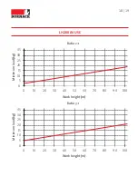
Page 17: ... the function of the LH200 To be able to lower the load when operated from below the load must e g have a minimum weight of approx 5 kg at a ratio of 1 1 and a lift height of 30 m 0 5 10 15 20 25 30 35 0 10 20 30 40 50 60 70 80 90 100 Mindestlast kg Arbeitshöhe m Übersetzung 1 1 Ratio 1 1 Work height m Minimum load kg ...

Page 18: ... 30 40 50 60 70 80 90 100 Mindestlast kg Arbeitshöhe m Übersetzung 3 1 0 5 10 15 20 25 30 35 0 10 20 30 40 50 60 70 80 90 100 Mindestlast kg Arbeitshöhe m Übersetzung 2 1 Ratio 2 1 Work height m Minimum load kg Ratio 3 1 Work height m Minimum load kg ...

Page 19: ...0 40 50 60 70 80 90 100 Mindestlast kg Arbeitshöhe m Übersetzung 4 1 0 5 10 15 20 25 30 35 0 10 20 30 40 50 60 70 80 90 100 Mindestlast kg Arbeitshöhe m Übersetzung 5 1 Ratio 4 1 Work height m Minimum load kg Ratio 5 1 Work height m Minimum load kg ...

Page 20: ...must have been briefed about the possible risks associated with its use If it is no longer possible to position the load in a controlled manner the device needs to be serviced by the manufacturer When operating the LH200 in areas where there is a risk of falls the oper ator must wear fall protection equip ment Health impairments can jeopardise the safety of the user when working at heights or dept...

Page 21: ...e sponding certificate The result must be documented in the test card at the end of these instructions SALES The dealer must ensure that the orig inal instructions and its translation in the language of the designated country are supplied The respective translation must be authorised by BORNACK SERVICE If you have any further questions about this product or other BORNACK services such as Risk anal...

Page 22: ...or delicates Then rinse carefully and allow to dry in the air Other cleaning agents are not allowed If disinfection is necessary please contact the e mail hotline info bornack de If the product comes into contact with salt water keep it wet until it can be rinsed with plenty of distilled water Use compressed air to blow on the unit if necessary LIFE SPAN The following recommendation applies for th...

Page 23: ... by BORNACK Only original spare parts from the manufacturer may be used STORAGE Dry wet equipment before storage Store in a dry place away from direct sunlight Do not store equipment near radiators Permanent exposure to temperatures below 0 C or above 50 C has a nega tive impact on the strength of the textile material and shortens the life span Do not allow equipment to come into contact with aggr...

Page 24: ...ful load Manufacturer address Contact Data matrix Observe read the instructions Identification rope Data matrix Production date Serial number Charge Size Identification basic unit Warning risk of hand injuries Warning rollers run in the opposite direction Warning suspended load Warning danger zone Protect your hands Wear a helmet Warning risk of falling Warning falling objects CE symbol ...

Page 25: ... described below Product type Load holder Product name LH200 Charge see label right Serial number see label right Production date see label right complies with the relevant provisions of the EC Directive 2006 42 EC on machinery Applied harmonised norms EN ISO 12100 2010 Safety of machinery General principles for design EN 13157 2004 A1 2009 Safety Hand powered cranes Authorised representative for ...

Page 26: ...TORING ___________________________________________________________ ___________________________________________________________ ___________________________________________________________ ___________________________________________________________ ___________________________________________________________ ___________________________________________________________ _________________________________...

Page 27: ...lean Identification legible No deformed parts No cracks in load bearing parts No wear abrasion No corrosion No foreign bodies within the unit Does the pulley rotate smoothly Centrifugal force mechanism blocks when the pull rope is jerked All pins on the pulley are in place and tight Continued on the next page ...

Page 28: ...4 5 6 7 8 9 10 Cover over the mechanical part undamaged Cover below the cover of the mechanical part undamaged Lock washers of the rollers are in place and undamaged Rivets are undamaged and tight Screw connections tight Screw heads nuts secured Continued on the next page ...

Page 29: ... Complete and clean Identification legible No knots in the rope Rope unworn no wear Undamaged Rope seam complete and undamaged Rope not damaged or worn near the connector OK Blocked T E S T C A R D FOR ANNUAL MONITORING Please complete ...

Page 30: ...30 31 Notes ...

Page 31: ...EN Notes ...

Page 32: ...k de www bornack de FALLSTOP Safety equipment for securing and rescuing at heights and depths SAFEPOINT Planning and assembly of stationary securing systems BORNACK Subject to technical changes Reprinting or duplication even of excerpts is only permitted with written consent Status 04 2022 GAL Art No 8000161_EN jba ...

Reviews: