18
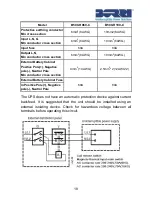
Model
B500-R060-C
B500-R100-C
Protective earthing conductor
Min cross section
6mm
2
(8AWG)
10mm2(6AWG)
Input L, N, G
Min conductor cross section
6mm
2
(8AWG)
10mm
2
(6AWG)
Input fuse
60A
80A
Output L,N,
Min conductor cross section
6mm
2
(8AWG)
10mm
2
(6AWG)
External Battery Cabinet
Positive Pole(+), Negative
pole(-), Neutral Pole
Min conductor cross section
4mm
2
(10AWG)
2.5mm
2
*2
(12AWG*2)
External Battery Cabinet Fuse
60A
80A
in Positive Pole(+), Negative
pole(-), Neutral Pole
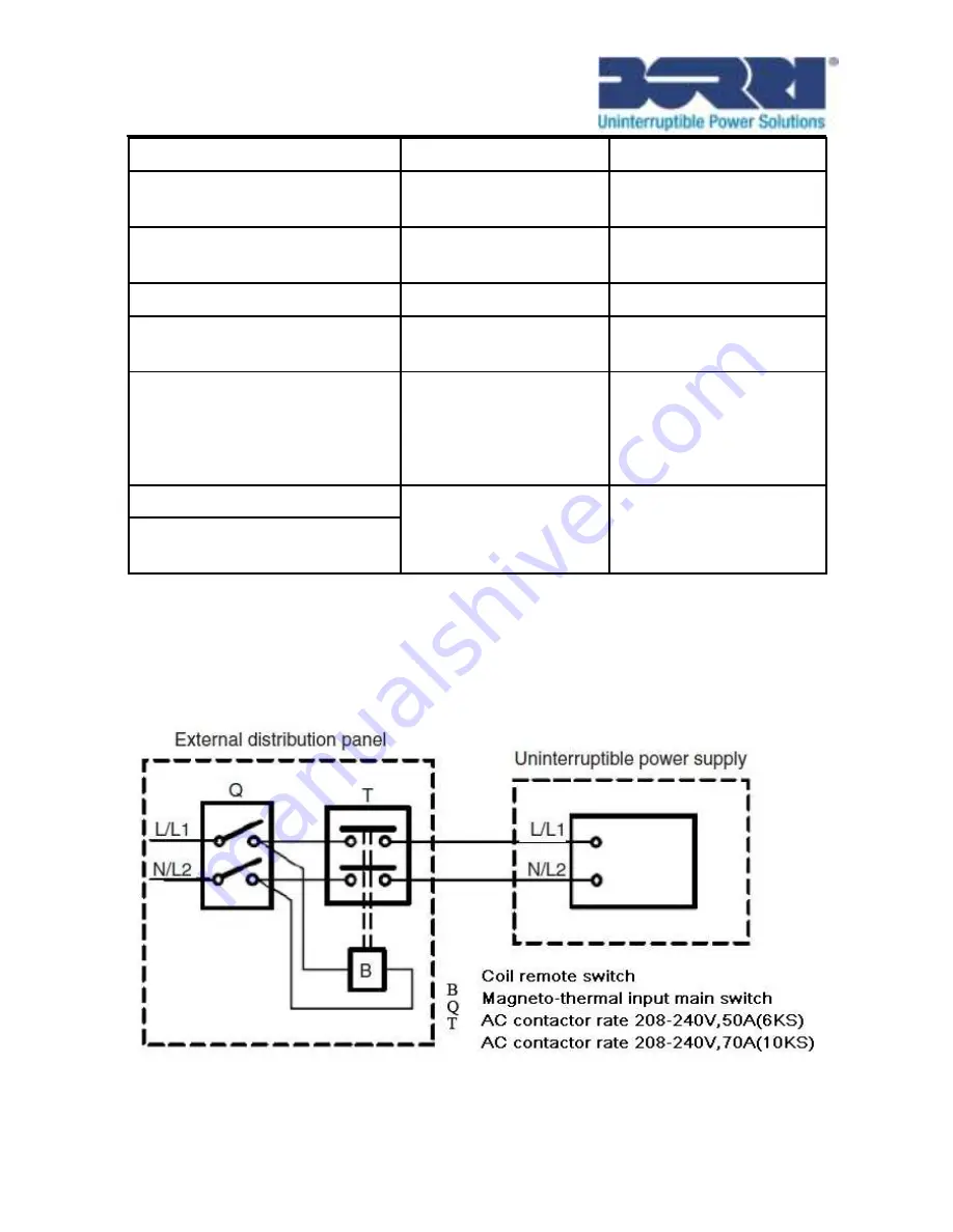
The UPS does not have an automatic protection device against current
backfeed. It is suggested that the unit should be installed using an
external isolating device. Check for hazardous voltage between all
terminals before operating this circuit.
Summary of Contents for B500-R060-C
Page 1: ...B500 Online UPS User Manual B500 R060 C B500 R100 C 208 220 230 240VAC ...
Page 2: ......
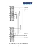
Page 29: ...25 Fig 4 9 Parallel systerm wiring diagram of B500 R060 C ...
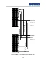
Page 30: ...26 Fig 4 10 Parallel systerm wiring diagram of B500 R100 C ...
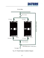
Page 31: ...27 Fig 4 11 Parallel System Installation Diagram ...
Page 43: ...39 Fig 5 14 Main menu tree ...
Page 50: ...46 ...


