29
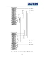
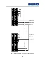
5) Connect the cable and wire of the added UPS according to
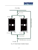
fig4-9 ,fig4-10 and fig4-11.
6) Switch on the input breakers and mains breaker, and make
sure that each UPS in the parallel system works correctly in
bypass mode.
7) Switch on the O/P breakers and main O/P breaker
,
transfer the
mains mechanical switch or static switch from Utility to the
output of the parallel system.
8) Press and hold the
button for either one of UPS in the
parallel system. Both UPS will turn on automatically, after which,
the parallel system will work in Line mode.
How to remove a single UPS from a parallel system:
1) Firstly set up a mains mechanical switch or static switch at the
output of the parallel system as fig4-11.
2) Ensure the bypass function of both UPS units is set as
“Enabled”. Press and hold the
button to turn off the parallel
system, and the system will shift into bypass mode.
3) Transfer the mains mechanical switch or static switch from the
output of the parallel system to Utility, then switch off all input
and output breakers and mains breakers for the two UPS, and
the UPS will shut down completely.
4) Switch off the mains breaker and main O/P breaker for the
\parallel system.
5) Remove the UPS and related components such as cables,
breakers. etc which are to be removed from the parallel system.
6) Switch on the mains breaker and input breaker of the remaining
UPS. Ensure the UPS works in bypass mode.
7) Switch on the O/P breaker and the main O/P breaker.
8) Transfer the mains mechanical switch or static switch from
Utility to the output of the UPS. Press and hold the
button to
turn on the UPS.
Summary of Contents for B500-R060-C
Page 1: ...B500 Online UPS User Manual B500 R060 C B500 R100 C 208 220 230 240VAC ...
Page 2: ......
Page 29: ...25 Fig 4 9 Parallel systerm wiring diagram of B500 R060 C ...
Page 30: ...26 Fig 4 10 Parallel systerm wiring diagram of B500 R100 C ...
Page 31: ...27 Fig 4 11 Parallel System Installation Diagram ...
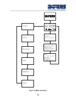
Page 43: ...39 Fig 5 14 Main menu tree ...
Page 50: ...46 ...

