background image

UPSaver

 installation and start-up


OMH44149 REV. C 

89


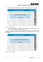
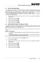
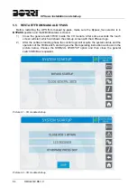
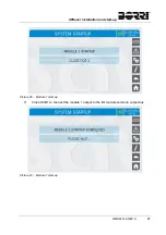
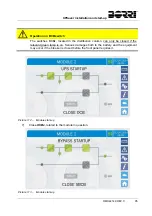
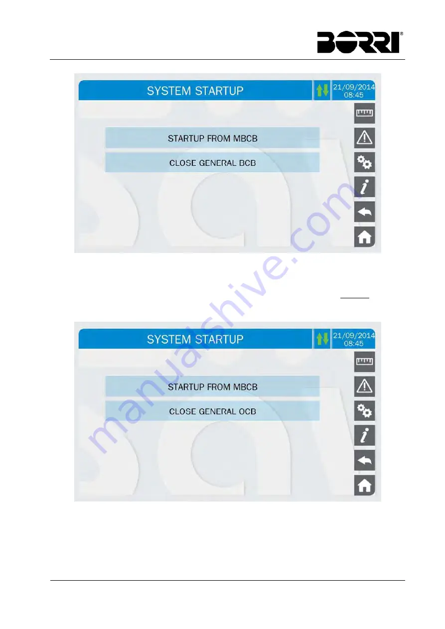
Picture 100 – 

Start-up from MBCB 

9) 

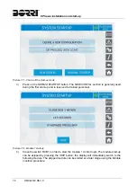
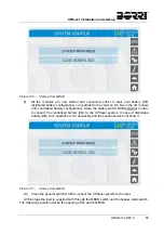
All the modules are now started and connected, either to their own battery (DB, 
distributed battery configuration) or in parallel to the common DC bus in the I/O module 
(CB, centralized battery configuration). Close the battery switch BCB (external) in order 
to connect the centralized battery (CB) to the 

UPSaver

 system. In case of distributed 

battery (DB) such operation is not necessary and the sequence does not show it. 


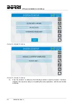
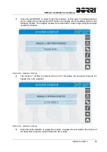
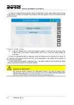
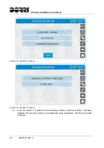
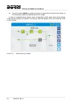
Picture 101 – 

Start-up from MBCB 

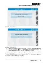
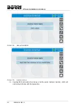
10)  Close the general switch OCB to connect the 

UPSaver

 system to the load. 

At this stage the load is supplied both through the MBCB switch and the bypass static switch. 

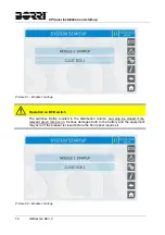
The following operation will be the opening of the switch MBCB.  

Summary of Contents for UPSaver 1000 kVa

Page 1: ... I Jet _________ __ ИБП Borri UPsaver руководство по эксплуатации Юниджет Постоянная ссылка на страницу https www uni jet com catalog istochniki besperebojnogo pitaniya on line ibp 100 kva borri upsaver html ...

Page 2: ...UPS OPERATING MANUAL UPSaver 400 1600 kVA ...

Page 3: ...WARNING This is a product for commercial and industrial application in the second environment installation restrictions or additional measures may be needed to prevent disturbance ...

Page 4: ...Lingua Language Pagina Page di Pag of Pag C Upgrade OMH44149 28 10 16 E Biancucci P Conti E 1 1 Codice Code OMH44147 UPS OPERATING MANUAL Index of the sections Code 1 WARNINGS AND GENERAL INFORMATION OMH44148 2 INSTALLATION AND START UP OMH44149 3 UPS USER MANUAL OMH44150 ...

Page 5: ......

Page 6: ...ssued Approvato Approved Lingua Language Pagina Page di Pag of Pag A First issue 10 02 15 G Senesi M Mancini E 1 7 Codice Code OMH44148 WARNINGS AND GENERAL INFORMATION Index 1 CONVENTIONS USED 3 2 DOCUMENTATION NOTES 4 3 CONTACTS 4 4 FACTORY WARRANTY 5 5 LIMITATION OF LIABILITY 7 ...

Page 7: ...Warnings and general information 2 OMH44148 REV A ...

Page 8: ... and property HAZARD HAZARD statements contain characteristics and basic instructions for the safety of persons Non compliance with such indications may cause serious injury or death WARNING WARNING statements contain characteristics and basic instructions for the safety of persons Non compliance with such indications may cause injury CAUTION CAUTION statements contain characteristics and importan...

Page 9: ...se contact the manufacturer of the device whose details are available in the Contacts section 3 CONTACTS For any information about the UPS systems manufactured by BORRI please contact Borri S p A Via 8 Marzo 2 52010 Soci Bibbiena AREZZO Tel 0575 5351 Fax 0575 561438 info borri it www borri it For help with technical problems or for information concerning device use and maintenance please contact t...

Page 10: ... In case of service performed following a call made by mistake or in case our technicians incur extra time and or costs due to the site inaccessibility or due to work interruptions required by the customer such costs will be invoiced in accordance with ANIE rates CLASS III COLUMN B Modes required a In the event of a fault covered by the warranty the customer shall notify Borri S p A in writing of ...

Page 11: ...ding failed operation of the air conditioning system etc Non compliance with applicable safety standards Force majeure e g lightning surges natural disasters fire acts of war riots etc Fall or displacement due to incorrect installation Ordinary wear caused by proper and continuous use of the device b Protective devices inside the units fuses and dischargers are also excluded from the warranty unle...

Page 12: ...nd therefore hazardous The manufacturer cannot be held responsible for possible damage arising from improper erroneous or unreasonable usage Borri assumes responsibility for the equipment in its original configuration Any intervention that alters the structure or the operating cycle of the equipment must be carried out and authorized directly by Borri Borri will not be held responsible for the con...

Page 13: ......

Page 14: ...WARNINGS 12 2 3 1 General warnings 12 2 3 2 Personnel 12 2 3 3 Transport and handling 12 2 3 4 Installation 12 2 3 5 Electrical connection 13 2 3 6 Operation 14 2 3 7 Maintenance 15 2 3 8 Storage 16 2 4 ENVIRONMENTAL PROTECTION 16 2 4 1 ISO 14001 certification 16 2 4 2 Recycling of packing materials 16 2 4 3 Device disposal 16 3 INSTALLATION 17 3 1 RECEIPT OF THE UPS 17 3 1 1 Storage 17 3 2 HANDLI...

Page 15: ...les 54 4 ELECTRICAL CONNECTION 56 4 1 CONNECTING THE POWER CABLES 57 4 2 BACK FEED PROTECTION DEVICE 59 4 3 TERMINAL BOARDS 60 4 3 1 Connection bars position 68 4 4 INTERFACE CARDS 70 4 5 CONNECTING THE AUXILIARY CABLES 70 4 5 1 DIESEL MODE activation 71 4 5 2 External Bypass_SW contact 71 4 5 3 Remote shut down EPO 71 4 5 4 Battery switch auxiliary contact 71 4 5 5 External manual bypass 71 4 5 6...

Page 16: ...dule top cable entry with centr battery and distributed static switches CB DSB 27 Picture 18 UPSaver 1400 kVA I O module top cable entry with centr battery and distributed static switches CB DSB 28 Picture 19 UPSaver 1600 kVA I O module with distributed static switches DB DSB 28 Picture 20 I O module breakers position up to 800kVA 29 Picture 21 I O module breakers position 1000 1200kVA 29 Picture ...

Page 17: ...UPSaver I O module terminal boards bottom cables entry 60 Picture 60 600 800kVA UPSaver detail of the I O module power terminals bottom cables entry 60 Picture 61 600 800kVA UPSaver I O module neutral connection bar bottom cables entry 61 Picture 62 600 800kVA UPSaver I O module earth connection bar bottom cables entry 61 Picture 63 600 800kVA UPSaver I O module terminal boards bottom cables entry...

Page 18: ...cture 89 Start up completed 82 Picture 90 Flow diagram 82 Picture 91 I O module start up 84 Picture 92 I O module start up 84 Picture 93 Module 1 start up 85 Picture 94 Module 1 start up 85 Picture 95 Module 1 start up 86 Picture 96 Module 1 start up 87 Picture 97 Module 1 start up 87 Picture 98 Module n start up 88 Picture 99 Module n start up 88 Picture 100 Start up from MBCB 89 Picture 101 Star...

Page 19: ...UPSaver installation and start up 6 OMH44149 REV C Picture 112 Module start up 95 Picture 113 Module start up 95 Picture 114 Module start up completed 96 ...

Page 20: ...UPSaver installation and start up OMH44149 REV C 7 ...

Page 21: ...gurations Storing documentation This manual and any other supporting technical documentation relating to the product must be stored and made accessible to personnel in the immediate vicinity of the UPS Further information In the event that the information provided in this manual is not sufficiently exhaustive please contact the manufacturer of the device whose details are available in the Contacts...

Page 22: ...iption of the parts composing the UPS and to guide the installer or the user through the installation of the unit in its using environment The installer or the user must read and correctly perform the instructions included in the present manual with particular reference to the requirements regarding safety in compliance with the current regulations Read the technical documentation Before installin...

Page 23: ...4 800 004 UPSaver GPU UPS RETE 1 MAINS 1 NETZ 1 Uin Vac Iin A RETE 2 MAINS 2 NETZ 2 800kVA 3Φ N Frequenza Frequency Frequenz N Serie Serial number Seriennummer F13S09001 Uout Vac Iout A Frequenza Frequency Frequenz Potenza Power rating Leistung Articolo Code Code Service www borri it Numero unità Unit number Stuck 690 According to ISO9001 2008 ISO14001 kg Made in ITALY Picture 1 UPSaver rating pla...

Page 24: ... the rating plate is integrated with an additional section which indicates the possible system configurations on the basis of the number of installed power modules see following picture The system test configuration is marked with a tick the plate can be replaced in case of increase or decrease of the UPS rated power that is in case power modules are added or removed 200 kVA 400 kVA 600 kVA 800 kV...

Page 25: ...is not uniformly distributed Pay attention when lifting Please inspect the device before installing it In case any damage is noticed from the conditions of the package and or from the outside appearance of the equipment contact the shipping company or your dealer immediately The damage statement must be made within 6 days from receipt of the product and must be notified to the shipping carrier dir...

Page 26: ...other sources strong electromagnetic fields radioactive levels higher than those of the natural environment fungus insects vermin Use authorized personnel only All transport installation and start up operations must be carried out by qualified and trained personnel The installation of The UPSaver UPS must be carried out by authorized personnel in compliance with national and local regulations Do n...

Page 27: ...DC battery voltage AC mains voltage AC bypass voltage Injury hazard due to electric shock The device is subject to high voltages thus all safety instructions must be scrupulously adhered to before performing any operation on the UPSaver UPS Isolate the battery via DC circuit breakers before connecting it to the UPS Connect the ground cable to the relevant bar before carrying out any other connecti...

Page 28: ...re carrying out any maintenance operation the UPSaver UPS must be disconnected from AC and DC supply sources The device is provided with internal isolators which allow to isolate the internal power circuits However the voltages of the supply sources are present on the terminals To isolate the device completely provide external circuit breakers on the lines The device contains dangerous voltages ev...

Page 29: ...xtreme temperature variations bad ventilation conductive or radiant heat from other sources fungus insects vermin 2 4 ENVIRONMENTAL PROTECTION 2 4 1 ISO 14001 certification Borri S p A is particularly sensitive to the environmental impact of its products That is why the UPSaver UPS has been manufactured with cutting edge eco design criteria ISO 14001 certification Special care was taken in using f...

Page 30: ... package Danger to persons due to transport damages Mechanical damage to the electrical components constitutes a serious danger to persons and property In case of doubt regarding the non integrity of the package or of the product contained therein contact the manufacturer before carrying out the installation and or the start up 3 1 1 Storage The package normally ensures protection from humidity an...

Page 31: ...r during the transport of the UPS Cabinets must always be handled in upright position During loading and unloading operations always respect the indications regarding the device barycentre marked on the package To handle the UPS remove the lower front and rear panel and insert the forks of a fork lift Picture 3 Panels removal on I O module The I O module can be handled both from the front and from...

Page 32: ...In order to handle the power module remove the front and rear covers and the two front triangular supports which would otherwise obstruct the way to the fork lift s forks Picture 5 Panels removal on power module After having removed the panels insert the fork lift and move the power module ...

Page 33: ...UPSaver installation and start up 20 OMH44149 REV C Picture 6 Handling of the power module ...

Page 34: ... the specific instructions 3 3 1 UPSaver basic configuration As outlined in the previous paragraphs the UPSaver system is essentially composed by two modular elements power module input output I O module The input output module I O is composed of a central section containing the connection terminal boards the sectioning devices and the centralized static switches when provided It is furthermore pr...

Page 35: ... REV C DSB Distributed Static Bypass switch Each power module which compose the UPSaver UPS is provide with its own bypass static switch 3 3 2 Base plan static load and weights Picture 7 Power module base plan Picture 8 600kVA I O module base plan ...

Page 36: ...200kVA I O module base plan The previous picture for what concern the 1200 kVA I O module is strictly related to the system configuration with distributed battery static switch DB DSB DB CSB Picture 10 1200kVA I O module base plan with centralized battery static switch ...

Page 37: ...UPSaver installation and start up 24 OMH44149 REV C Picture 11 1400kVA I O module base plan Picture 12 1600kVA I O module base plan ...

Page 38: ...B DSB DB CSB DB DSB Power module 570 1030 400 kVA I O module 660 650 650 520 620 610 610 490 600 kVA I O module 690 680 680 550 650 640 640 520 800 kVA I O module 780 770 770 640 560 560 560 460 1000 kVA I O module 1140 890 990 740 670 520 720 540 1200 kVA I O module 1170 920 1020 770 690 540 740 560 1400 kVA I O module Contact the manufacturer 1450 Contact the manufacturer 560 1600 kVA I O module...

Page 39: ...UPSaver installation and start up 26 OMH44149 REV C Picture 14 UPSaver I O module up to 600 kVA Picture 15 UPSaver 800 kVA and 1200kVA DB DSB DB CSB I O module ...

Page 40: ...d start up OMH44149 REV C 27 Picture 16 UPSaver 1000 1200 kVA I O module with centr battery st sw CB DSB CB CSB Picture 17 UPSaver 1200 kVA I O module top cable entry with centr battery and distributed static switches CB DSB ...

Page 41: ...and start up 28 OMH44149 REV C Picture 18 UPSaver 1400 kVA I O module top cable entry with centr battery and distributed static switches CB DSB Picture 19 UPSaver 1600 kVA I O module with distributed static switches DB DSB ...

Page 42: ...UPSaver installation and start up OMH44149 REV C 29 Picture 20 I O module breakers position up to 800kVA Picture 21 I O module breakers position 1000 1200kVA ...

Page 43: ...UPSaver installation and start up 30 OMH44149 REV C Picture 22 I O module breakers position 1200 1400kVA Picture 23 I O module breakers position 1600kVA ...

Page 44: ...UPSaver installation and start up OMH44149 REV C 31 Picture 24 I O module distribution columns breakers position up to 1200kVA Picture 25 1400kVA I O module distribution columns breakers position ...

Page 45: ...UPSaver installation and start up 32 OMH44149 REV C Picture 26 1600kVA I O module distribution columns breakers position Picture 27 400kVA UPSaver layout Picture 28 600kVA UPSaver layout ...

Page 46: ...UPSaver installation and start up OMH44149 REV C 33 Picture 29 800kVA UPSaver layout Picture 30 1000kVA UPSaver layout Picture 31 1200kVA UPSaver layout ...

Page 47: ...UPSaver installation and start up 34 OMH44149 REV C Picture 32 Battery centralized 1200kVA UPSaver layout Picture 33 Battery centralized 1400kVA UPSaver layout Picture 34 1600kVA UPSaver layout ...

Page 48: ...0 1200 1400 1600 Width mm L CB CSB 2350 2950 3900 4850 5450 6400 CB DSB DB CSB 4500 5100 DB DSB 7000 7600 Depth mm P All 970 Height mm H All 2100 2150 1 1 The 1600kVA I O module is provided of an additional iron frame h 50 mm for the routing of the interconnection cables with the power modules ...

Page 49: ...es the same installation conditions apply as indicated in the table below Picture 35 Wall clearances A mm B mm C mm D mm Recommended clearances 50 1200 50 600 Minimum clearances 0 1200 0 400 The table below shows the air volume required for an optimal ventilation and cooling of the equipment The values are referred to the on line double conversion operation with rated load applied Power kVA 400 60...

Page 50: ...NO Classification of biological conditions EN 60721 3 3 Environmental parameter Class 3B1 3B2 3B3 a Flora NO Presence of mildew fungus etc Presence of mildew fungus etc b Fauna NO Presence of rodents and other animals that are harmful to products excluding termites Presence of rodents and other animals that are harmful to products including termites Classification of mechanically active substances...

Page 51: ...y X Places where atmosphere is permanently monitored X Places located in rural and urban regions where industrial activities are few and where traffic is moderate X Places located in urban regions with industrial activities and or considerable traffic X Places in proximity to industrial sources with chemical emissions X Places located in industrial installations Emissions of highly concentrated ch...

Page 52: ...s a opening to where the interconnection cables between the I O module and the power modules can be laid When the floating floor is not installed for top cables entry for example it will be necessary to install cables routing bases on the sides of the I O module just where the power modules will be placed Picture 36 Cable routing base A Installation example of cables routing bases for a 800 kVA UP...

Page 53: ...49 REV C 3 4 2 Floor fixing The floor fixing method for the various modules which compose the UPSaver system varies depending on the UPS bearing surface being it a concrete floor or a iron base Picture 38 Floor fixing Picture 39 Iron base fixing ...

Page 54: ...ecessary to lay and connect the interconnection cables among the modules The pictures which follow show the cable routing on the metal bases in case a floating floor is present the cables will obviously run in the available between the system bearing surface and the underlying concrete floor Picture 40 Cabinet base plates removal Picture 41 Interconnection cables connection points ...

Page 55: ...the interconnection cables connection and routing are completed it is possible to proceed to the positioning of the power modules pay attention to place the module in such a way that the fixing holes in the module frame coincide with the holes prearranged on the cables routing bases or on the iron base Picture 43 Positioning the power module ...

Page 56: ...terally down at each cabinet are provided with threaded holes specifically arranged to mechanically connect the frames It is suggested to connect the cabinets both at the front and the rear using a M8x20 hexagonal head bolt Picture 44 Cabinets front fixing Picture 45 Cabinet rear fixing Then the cabinets can be correctly aligned by connecting the upper cross bars through the specific metal plates ...

Page 57: ...UPSaver installation and start up 44 OMH44149 REV C Picture 46 UPS cabinets upper fixing ...

Page 58: ... A terminals protection plate B cables passage covering plate C In order to ease cables connection work it is advisable to remove the lower power conversion module D and the side protection plate E Picture 47 Parts to be removed for cables connection Picture 48 Power modules with parts removed The connection terminals are available on the front of the cabinet and located as shown in the following ...

Page 59: ...UPSaver installation and start up 46 OMH44149 REV C Picture 49 Power module cables terminals ...

Page 60: ...onnection terminals DISTRIBUTED BATTERY I O module 1 Power module R Mx R DC BUS R Mx R Bx B BATTERY 3 Nx N Bx B 1 In the distribution column the terminals are identified as Mx where x is the number which identifies which power module must be connected to those terminals 2 The interconnection of the output neutral conductor is not provided The connection is performed inside the power module using a...

Page 61: ...abinet front doors are provided that must be removed Picture 50 Bus cable raceways Picture 51 Removing the bus cable raceways Both the I O module and the power modules are equipped with a specific connection card provided with two connectors which are doubled at each end see following picture The cable must be connected in such a way that the A connector of one card is connected to the B connector...

Page 62: ...tallation and start up OMH44149 REV C 49 Picture 52 Bus cable connection cards The cable must be connected so as to form a loop thus to guarantee the first fault system immunity Picture 53 Connecting the bus cable ...

Page 63: ...UPSaver installation and start up 50 OMH44149 REV C Once the cable has been connected fix it to the cabinet upper cross bars and put the metal raceways back in place Picture 54 Raceways re positioning ...

Page 64: ... switches that are used to supply and or terminate the data connection among the modules Picture 55 Detail of the parallel card dip switches The dip switches must be set according to the physical position of the device within the system In particular the following switches must always be set to OFF switch S2 dip 4 switch S3 dip 4 switch S1 dip 9 switch DSW1 dip 1 ...

Page 65: ... the various devices will be as follows DIP SW MODULE I O 1 2 3 S1 1 ON ON OFF OFF 2 ON ON OFF OFF 3 ON ON OFF OFF 4 ON ON OFF OFF 5 ON ON OFF OFF 6 ON ON OFF OFF 7 ON ON OFF OFF 8 ON ON OFF OFF 9 ON ON OFF OFF 10 OFF OFF OFF OFF S2 1 ON ON OFF OFF 2 ON ON OFF OFF 3 ON ON OFF OFF 4 OFF OFF OFF OFF S3 1 ON ON OFF OFF 2 ON ON OFF OFF 3 ON ON OFF OFF 4 OFF OFF OFF OFF DSW1 1 OFF OFF OFF OFF 2 ON ON O...

Page 66: ... ON OFF OFF ON 3 OFF ON OFF OFF ON 4 OFF ON OFF OFF ON 5 OFF ON OFF OFF ON 6 OFF ON OFF OFF ON 7 OFF ON OFF OFF ON 8 OFF ON OFF OFF ON 9 OFF ON OFF OFF ON 10 OFF OFF OFF OFF OFF S2 1 OFF ON OFF OFF ON 2 OFF ON OFF OFF ON 3 OFF ON OFF OFF ON 4 OFF OFF OFF OFF OFF S3 1 OFF ON OFF OFF ON 2 OFF ON OFF OFF ON 3 OFF ON OFF OFF ON 4 OFF OFF OFF OFF OFF DSW1 1 OFF OFF OFF OFF OFF 2 ON ON ON ON ON ...

Page 67: ...X1 1 12 SRC 2 X1 5 12 SRC 2 X22 1 X2 1 MODULE 2 X26 1 X2 1 MODULE 6 X22 2 X2 2 X26 2 X2 2 X22 3 X2 3 X26 3 X2 3 X22 4 X2 4 X26 4 X2 4 X32 1 5 EXT INP 1 X36 1 5 EXT INP 1 X32 2 6 EXT INP X36 2 6 EXT INP XB2 1 9 EXT INP XB6 1 9 EXT INP XB2 2 10 EXT INP XB6 2 10 EXT INP L2 1 11 SRC 2 2 L6 1 11 SRC 2 2 X1 2 12 SRC 2 X1 6 12 SRC 2 X23 1 X2 1 MODULE 3 X27 1 X2 1 MODULE 7 X23 2 X2 2 X27 2 X2 2 X23 3 X2 3...

Page 68: ...start up OMH44149 REV C 55 The signal terminal boards or connectors in the I O module are located at the bottom of the right hand side distribution column as indicated in the picture below Picture 58 I O module signal position ...

Page 69: ...earing in mind technical financial and safety aspects The selection and the sizing of cables from a technical viewpoint depend on the voltage on the current absorbed by the UPS on the bypass line and on the batteries on the ambient temperature and on the voltage drop Finally the kind of cable laying must be taken into particular consideration For more explanations regarding the selection and the s...

Page 70: ...from the rectifier supply mains 1 L1 1 L2 1 L3 Neutral conductors of the input lines 1 N 2 N AC supply from the bypass supply mains 2 L1 2 L2 2 L3 AC output to the loads 3 L1 3 L2 3 L3 3 N Injury hazard due to electric shock Very high voltages are present at the ends of the cables coming from the battery Isolate the battery via DC circuit breakers before connecting it to the UPS Connect the ground...

Page 71: ...ral point N 2 Suggested cables for centralized battery configuration single battery 3 Suggested cables for distributed battery configuration one battery for each power module The data detailed in the table above are indicative only In designing the cables the rated current carrying capacities given by the CEI UNEL35024 1 table have been taken into account related to copper cables with PVC insulati...

Page 72: ...attery charger in operation The use of an external device forces the user to separate the UPS supply lines rectifier and bypass if the flexibility and availability of the UPS are supposed to be kept unaltered The UPSaver systems with centralized static bypass switch are provided with voltage free contacts which can be used to operate the shunt trip coil of the external sectioning device the extern...

Page 73: ... cables and of the auxiliary connections The cables entry can be provided either from the bottom or the top on the basis of the plant requirements the UPSaver basic configuration provides for bottom cables entry Picture 59 600 800kVA UPSaver I O module terminal boards bottom cables entry Picture 60 600 800kVA UPSaver detail of the I O module power terminals bottom cables entry ...

Page 74: ...installation and start up OMH44149 REV C 61 Picture 61 600 800kVA UPSaver I O module neutral connection bar bottom cables entry Picture 62 600 800kVA UPSaver I O module earth connection bar bottom cables entry ...

Page 75: ...nstallation and start up 62 OMH44149 REV C Picture 63 600 800kVA UPSaver I O module terminal boards bottom cables entry Picture 64 600 800kVA UPSaver detail of the I O module power terminals bottom cables entry ...

Page 76: ...er installation and start up OMH44149 REV C 63 Picture 65 600 800kVA UPSaver I O module neutral connection bar top cables entry Picture 66 600 800kVA UPSaver I O module earth connection bar top cables entry ...

Page 77: ...r installation and start up 64 OMH44149 REV C Picture 67 1200kVA UPSaver I O module terminal boards bottom cables entry Picture 68 1200kVA UPSaver detail of the I O module power terminals bottom cables entry ...

Page 78: ... installation and start up OMH44149 REV C 65 Picture 69 1200kVA UPSaver centralized battery power terminals bottom cables entry Picture 70 1200kVA UPSaver I O module neutral connection bar bottom cables entry ...

Page 79: ...aver installation and start up 66 OMH44149 REV C Picture 71 1200kVA 1400kVA UPSaver centralized battery power terminals top cables entry Picture 72 1600kVA UPSaver detail of the I O module power terminals ...

Page 80: ...is arranged for input and putput power bus bars while for the bypass line and the batteries are used copper bars and terminals repsectively The configuration of the power bus bars can be varied during the manufacturing phase therefore the previous pictures must be considered purely indicative Contact the manufacturer for detailed drawings related to the power connections ...

Page 81: ...base For top cables entry the distance is given from the roof cables entry plate The distance is referred to the first available hole Bottom cables entry Distance from ground mm Connection Bar I O 800kVA I O 1200kVA I O 1600kVA Rectifier L1 1060 415 Contact the manufacturer L2 900 415 L3 770 415 Bypass L1 680 1235 L2 520 1235 L3 380 1235 UPS output L1 1060 715 L2 900 715 L3 770 715 Battery B 415 5...

Page 82: ...istance from roof mm Connection Barra I O 800kVA I O 1200kVA I O 1600kVA Rectifier L1 870 Contact the manufacturer Contact the manufacturer L2 710 L3 575 Bypass L1 490 L2 320 L3 185 UPS output L1 870 L2 710 L3 575 Battery B 215 N B Rect Byp Out Neutral N 1010 PE Earth 155 ...

Page 83: ... INP used for connecting the external contacts EXT INP 3 OPTIONAL used for connecting the external contacts SRC 2 relay card for the remote signalisation of the UPS status and alarms THERMAL PROBE OPTION used for connecting an external thermal probe in order to acquire the temperature of the battery room Picture 74 Location of the UPSaver interface cards 4 5 CONNECTING THE AUXILIARY CABLES The UPS...

Page 84: ... inverter to bypass or vice versa in case of ECO MODE where the bypass is the priority line 4 5 3 Remote shut down EPO Auxiliary EPO contact terminals 7 8 card EXT INP The voltage supply to the loads can be interrupted from a remote location by using this contact i e for safety requirements A normally closed contact is required when this contact is open the static inverter and by pass switches are...

Page 85: ...RL1 Alarm A30 COMMON ALARM Not energized if alarm is present 2 3 Closed DL1 On 1 2 Open RL2 Alarm A1 MAINS FAULT Not energized if alarm is present 5 6 Closed DL2 On 4 5 Open RL3 Alarm A9 BATTERY AUT END Not energized if alarm is present 8 9 Closed DL3 On 7 8 Open RL4 Alarm A13 INV OUT OF TOL Not energized if alarm is present 11 12 Closed DL4 On 10 11 Open RL5 NORMAL MODE Alarm A16 BYPASS LOAD Not ...

Page 86: ...ice whose details are available in the Contacts section 5 1 PRELIMINARY CHECKS Before starting up the unit make sure that all installation and electric connection works have been performed professionally all power and control cables have been properly and tightly connected to the relevant terminal boards the ground cable is properly connected the battery polarity is correct and the voltage is with...

Page 87: ...attery breaker BCB before it s required by the front panel Serious damages to the UPS internal parts and or to the battery may occur The UPSaver system start up is completely guided the indications available by the touch screen allows the complete comprehension of the various steps and helps the operator in performing the requested operations in the correct sequence However all the sectioning devi...

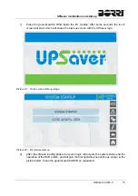
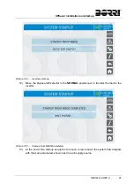
Page 88: ...ill shown the start up screen with the UPSaver logo Picture 75 Touch screen start up image Picture 76 I O module start up 2 After the software loading phase the control logic will acquire the system status and the operation of the RCB switch and will give the first operating instruction as shown in the picture below Close the general switch SBCB as requested ...

Page 89: ...uring the first start up and is reserved to trained personnel Picture 78 Module 1 start up 4 Close the switch RCB1 in order to start the module 1 control logic The module start up can be skipped by pressing the SKIP button the display will immediately switch to the following module The skipped module can be started at a later stage using the Module insertion procedure ...

Page 90: ...the green lamp located next to the battery switch BCB1 will turn on Close the switch BCB1 as requested In case of centralized battery configuration CB the BCBx closure connects the module x DC bus to the I O module common DC bus and subsequently to the battery by the closure of the general switch BCB In case of distributed battery configuration DC one battery bank for each module the BCBx closure ...

Page 91: ... Operation on BCB switch The switches BCBx located in the distribution column can only be closed if the relevant green lamp is on Serious damages both to the battery and the equipment may occur if the breaker is closed before the front panel requires it Picture 82 Module 1 start up ...

Page 92: ...ress the button SBCB1 to supply the module 1 bypass line and wait for the closure of the back feed contactor located inside the I O module In case of centralized static bypass switch configuration CSB single static switch located inside the I O module such phase is not present since the bypass line is not connected to the power modules Picture 84 Module 1 start up ...

Page 93: ...9 REV C Picture 85 Module n start up Picture 86 Module n start up 8 Once the module 1 is started or the following module in case the module 1 had been skipped the sequence will go on repeating the same operations until the last module is started ...

Page 94: ...el to the common DC bus in the I O module CB centralized battery configuration Close the battery switch BCB external in order to connect the centralized battery CB to the UPSaver system In case of distributed battery DB such operation is not necessary and the sequence does not show it Picture 88 Connection of the system to the load 10 Close the general switch OCB to connect the UPSaver system to t...

Page 95: ... start up 82 OMH44149 REV C Picture 89 Start up completed Picture 90 Flow diagram 11 At the end of the start up sequence the touch screen shown the system flow diagram with the main parameters shown next to each supply source ...

Page 96: ...eral switch BCB 4 Open the general switch RCB 5 Open the general switch SBCB 5 4 SWITCHING PROCEDURE TO MANUAL BYPASS The load is transferred to Manual Bypass with no interruption of supply to the loads In this configuration the system can be restarted via the return procedure from load on manual bypass without the need to de energize the loads Manual bypass To perform the switching procedure corr...

Page 97: ...I O module After some seconds the touch screen will start which will shown the start up screen with the UPSaver logo 2 After the software loading phase the control logic will acquire the system status and the operation of the RCB switch and will give the first operating instruction as shown in the picture below Choose the NORMAL STARTUP option and then close the general switch SBCB as requested Pi...

Page 98: ... the following module The skipped module can be started at a later stage using the Module insertion procedure Picture 93 Module 1 start up 4 The module 1 rectifier is started at the end of this phase the sequence requires the bypass line to be supplied Picture 94 Module 1 start up 5 Press the button SBCB1 to supply the module 1 bypass line and wait for the closure of the back feed contactor locate...

Page 99: ...se the switch BCB1 as requested In case of centralized battery configuration CB the BCBx closure connects the module x DC bus to the I O module common DC bus and subsequently to the battery by the closure of the general switch BCB In case of distributed battery configuration DC one battery bank for each module the BCBx closure connects the module x to its own battery Operation on BCB switch The sw...

Page 100: ...UPSaver installation and start up OMH44149 REV C 87 Picture 96 Module 1 start up 7 Close OCB1 to connect the module 1 output to the I O module common output bus Picture 97 Module 1 start up ...

Page 101: ...9 REV C Picture 98 Module n start up Picture 99 Module n start up 8 Once the module 1 is started or the following module in case the module 1 had been skipped the sequence will go on repeating the same operations until the last module is started ...

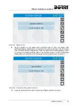
Page 102: ...figuration Close the battery switch BCB external in order to connect the centralized battery CB to the UPSaver system In case of distributed battery DB such operation is not necessary and the sequence does not show it Picture 101 Start up from MBCB 10 Close the general switch OCB to connect the UPSaver system to the load At this stage the load is supplied both through the MBCB switch and the bypas...

Page 103: ... and start up 90 OMH44149 REV C Picture 102 Start up from MBCB Picture 103 Inverters start up 11 Opening MCB will enable the start up of all the power modules inverters which will start and synchronize with the bypass line ...

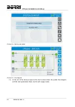
Page 104: ...up 12 Move the Bypass SW selector to the NORMAL position per to transfer the load to the inverter Picture 105 Start up from MBCB completed 13 At the end of the start up sequence the touch screen shown the system flow diagram with the main parameters shown next to each supply source ...

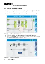
Page 105: ...g to the following procedure 1 From the Home page flow diagram press on the power module which is supposed to be started Picture 106 Identification of the module to start up 2 The touch screen will show the module flow diagram without any inscriptions 3 Close the switch RCBx related to the module in question and wait for the green LED which indicates that the mains is present to turn on Picture 10...

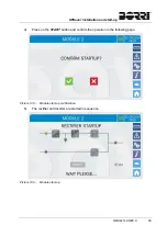
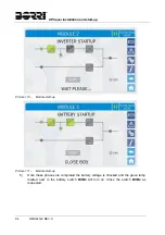
Page 106: ... start up OMH44149 REV C 93 4 Press on the START button and confirm the operation in the following page Picture 108 Module start up confirmation 5 The rectifier and inverter are started in sequence Picture 109 Module start up ...

Page 107: ...H44149 REV C Picture 110 Module start up Picture 111 Module start up 6 Once these phases are completed the battery voltage is checked and the green lamp located next to the battery switch BCBx will turn on Close the switch BCBx as requested ...

Page 108: ...n the distribution column can only be closed if the relevant green lamp is on Serious damages both to the battery and the equipment may occur if the breaker is closed before the front panel requires it Picture 112 Module start up 7 Close OCBx related to the module in question Picture 113 Module start up ...

Page 109: ...d wait for the closure of the back feed contactor located inside the I O module In case of centralized static bypass switch configuration CSB single static switch located inside the I O module such phase is not present since the bypass line is not connected to the power modules Picture 114 Module start up completed ...

Page 110: ... CONFIGURATIONS 11 3 2 1 CB CSB configuration 11 3 2 2 CB DSB configuration 12 3 2 3 DB CSB configuration 13 3 2 4 DB DSB configuration 13 3 3 OPERATING STATUS 14 3 3 1 DHE mode Double High Efficiency 14 3 3 1 1 Optimization of the efficiency by power modules rotation 16 3 3 2 VHE mode Very High Efficiency Line Interactive 17 3 3 3 ECO mode 17 3 3 4 UHE mode Ultra High Efficiency 18 3 3 5 Manual b...

Page 111: ...tralized battery 37 5 3 8 Centralized battery test 38 5 3 9 Setting the display network parameters 38 5 3 9 1 Setting the LAN parameters 38 5 3 9 2 Setting the NTP parameters 39 5 3 9 3 Setting the ModBus TCP IP and RS485 parameters 40 5 3 9 4 Modifying the parameters 40 5 3 10 Bypass Switch status 41 5 3 11 Modifying the operating mode LINE INTERACTIVE 42 5 3 12 Modifying the modules redundancy l...

Page 112: ...6 1 DISPLAYING THE MEASURES 50 6 2 DIAGNOSTICA DI BASE 51 6 2 1 Icons colours 51 6 2 2 Lista degli allarmi e degli stati 52 6 3 SETTINGS AND ADVANCED OPERATIONS 54 6 3 1 Resetting the device 54 6 3 2 Setting the battery 55 6 3 3 Battery test 55 6 3 4 New battery 56 6 4 POWER MODULE INFORMATION 57 6 4 1 Device information 57 6 4 2 Modular system information 57 6 4 3 Firmware release 57 7 FAULTS AND...

Page 113: ...cture 13 Battery discharging 16 Picture 14 VHE mode 17 Picture 15 ECO mode 17 Picture 16 UHE mode 18 Picture 17 UHE mode mains failure 18 Picture 18 Manual bypass 19 Picture 19 UPS front panel Home page 23 Picture 20 MEASURES section 25 Picture 21 Input measures page 25 Picture 22 ALARMS section 27 Picture 23 ALARMS section 27 Picture 24 History log page 1 28 Picture 25 History log page 2 29 Pictu...

Page 114: ... Picture 44 INFO section 45 Picture 45 Device information 45 Picture 46 Modules information 46 Picture 47 Parallel information 47 Picture 48 Parallel bus communication status 48 Picture 49 Firmware release 48 Picture 50 LINE INTERACTIVE parameters 49 Picture 51 Accessing the power module sections 50 Picture 52 MEASURES section power module 50 Picture 53 ALARMS section power modules 51 Picture 54 S...

Page 115: ...UPS user manual 6 OMH44150 REV B ...

Page 116: ... Storing documentation This manual and any other supporting technical documentation relating to the product must be stored and made accessible to personnel in the immediate vicinity of the UPS Further information In the event that the information provided in this manual is not sufficiently exhaustive please contact the manufacturer of the device whose details are available in the Contacts section ...

Page 117: ... strictly followed Injury hazard due to device failure Potentially hazardous situations may arise in case of UPS failure Do not use the device if visibly damaged Maintain the device regularly to identify possible failure Possible device damage Whenever work is carried out on the device make sure all actions are taken in order to avoid electrostatic discharges which might damage the electronic comp...

Page 118: ...upplied by the system Output voltage present The line connected to the UPS output is energized even during mains failure therefore in compliance with the prescriptions of IEC EN62040 1 2 the installer will have to identify the line or the plugs supplied by the UPS making the User aware of this fact Picture 1 1200 kVA UPSaver typical block diagram The picture above shows a typical block diagram of ...

Page 119: ...r at full load and the battery at the maximum charging current The battery charger logic is completely integrated in the rectifier s control electronics The battery is charged according to the DIN 41773 Standard every time it has been partially or completely discharged When its full capacity is restored it is disconnected from the DC bus by means of a static switch in order to save energy reduce t...

Page 120: ...B Distributed Battery One battery bank for each module that compose the UPSaver UPS is provided for The connection of the various batteries is carried out inside the I O module but each power module is provided with its own battery static switch CSB Centralized Static Bypass switch Only one bypass static switch is provided which is installed inside the I O cabinet DSB Distributed Static Bypass swi...

Page 121: ...lators BCBx located in the I O module side distribution columns Each module proportionally contributes to the battery charge which is charged in parallel by all the modules providing a fraction of the current The battery static switch is installed inside the I O module The bypass static switch is distributed therefore it is provided in each power module The pus buttons SBCBx which allows the opera...

Page 122: ...re independent from the others The isolators BCBx located in the distribution colums at the sides of the I O module directly connects the DC bus of each module to its battery The static bypass switch is single and centralized and is installed inside the I O module Picture 8 UPSaver DB CSB power module configuration The bypass static switch is not installed in the power module BPU 3 2 4 DB DSB conf...

Page 123: ...f the power modules bypass line are installed in the distribution columns Picture 10 UPSaver DB DSB power module configuration The power module is in its complete configuration being provided with both the bypass and the battery static switches 3 3 OPERATING STATUS The UPSaver UPS can be programmed ot operate in four different modes DHE Double High Efficiency VHE Very High Efficiency Line Interact...

Page 124: ...f lost capacity referred to the rated value Lost capacity 10 Additional charge for 12 hours Lost capacity between 10 and 20 Additional charge for 48 hours Lost capacity 20 Additional charge for 96 hours Such values complies with the recommendations of the main battery manufacturers Set the right battery capacity The UPS front panel allows the setting of the battery parameters including the rated c...

Page 125: ...uld the inverter fail or in case the Bypass_SW selector is manually operated the load is transferred to the bypass line and supplied via the bypass static switch The re transfer to inverter which represent the primary source in the DHE mode occurs automatically and without any interruptions once the anomaly is ceased 3 3 1 1 Optimization of the efficiency by power modules rotation In the DHE opera...

Page 126: ...unction can be enabled and is automatically managed by the above mentioned algorithm on the basis of both the load and AC supply conditions In case of mains outage or anomaly occurring on the bypass line the load is transferred to the inverter Picture 14 VHE mode 3 3 3 ECO mode Similarly to the VHE mode the load is supplied by the mains in the ECO mode as well it differs from the VHE mode because ...

Page 127: ...ently on in order to supply the control logic and safeguard the battery which would otherwise supply energy although in a very limited quantity Therefore the battery static switch is kept open and is operated only in case of mains failure Should the mains fail the inverter is started and the load is transferred through the static switch The disturbance on the output voltage is fully within both th...

Page 128: ...the switches are generally open both the general switches and those related to each power module and the only closed isolator is MBCB Follow the procedures contained in the manual The sequence of manual bypass switching and return must be carried out with respect to the procedure indicated in the installation and start up section The manufacturer cannot accept responsibility for damages arising fr...

Page 129: ...statico SBCBx Module output isolator OCBx Battery isolator BCBx Check the personnel training The use of the operation and control devices of the UPS is intended for authorized personnel only We recommend to check the training of the personnel responsible for the use and maintenance of the system 3 4 1 Isolators AC inputs battery and AC output The isolators provided on the UPS are used to isolate t...

Page 130: ...ely interrupting the loads supply It also shuts down the inverter Operate the command only in case of real emergency The components of the system are subject to a high stress when the emergency power off command is operated under load presence Use the emergency power off button only in case of real emergency Supply reset Reset the output supply only when the causes which led to the emergency shutd...

Page 131: ...nel is used for Verifying the device operating parameters Accessing the events log Displaying the device information Modifying the operating parameters The section through which the parameters can be modified is password protected in order to avoid the access by non authorized personnel ...

Page 132: ...cture 19 UPS front panel Home page 4 1 ICONS Browsing through the pages of the touch screen is possible through the six icons provided on the right hand side the icon with the up down arrows controls the display communication Icon Assigned functions Measures Enters the Measures section Alarms Enters the Alarms section and resets the buzzer if activated Settings Enters the Settings section Info Ent...

Page 133: ...ours are Light blue It indicates that the section is related to the UPSaver UPS therefore it will show the system data Dark blue The keys Measures Alarms Settings and Info turn dark blue when the module data display is entered by pressing one of the modules Grey The keys turn grey disabled when the key specific section is entered Red The Home and Alarms keys will turn red in case an alarm occurs F...

Page 134: ...arious sections of the control panel from the Home page directly 5 1 DISPLAYING THE MEASURES Press on the Measures icon to enter the main page Picture 20 MEASURES section The measures page of a specific section of the UPS is entered pressing one of the arrows A typical Measures page is shown below Picture 21 Input measures page ...

Page 135: ...ad percentage 1 Active power 1 kW Apparente power 1 kVA Frequency 0 1 Hz BYPASS Voltage 1 1 V Frequency 0 1 Hz INVERTER Voltage 1 1 V Frequency 0 1 Hz AC DC Rectifier output voltage 1 V BATTERy Voltage and current 1 V 1 A Rated capacity 1 Ah Residual autonomy 1 min 1 TEMPERATURE 2 Battery 0 1 C UPS 0 1 C 1 The voltage measures are always given referred to the phase to neutral value 2 The temperatu...

Page 136: ...story log can be selected Picture 22 ALARMS section 5 2 1 Displaying the operating status Press UPS status to show the UPS operating status which includes possible active alarms Picture 23 ALARMS section The current system status is shown in case the list is longer than the page capacity 8 lines it can be scrolled by sliding a finger on the screen ...

Page 137: ...s the relevant icon in the Home page will turn Orange or Red Light blue No active alarms Red Active alarms in the I O module while a page of one of the power modules sections is currently displayed The audible indicator if enabled is activated to show the occurred failure The audible alarm is silenced by pressing the Alarms icon Automatic erasure of alarms Should an alarm occur and then the condit...

Page 138: ...erisk indicates the automatic reset of the alarm The maximum number of events which can be shown is equal to 250 The events log can be scrolled by sliding a finger on the screen Picture 25 History log page 2 Pressing the key Save history to file will open the following page Picture 26 Saving the history log The touch screen automatically recognizes when an external memory support USB stick or SD c...

Page 139: ...ONFIGURATION ERROR A13 INVERTER OUT OF TOLERANCE A45 HIGH TEMPERATURE SSW A14 BYPASS WRONG SEQUENCE A46 REDUNDANCY LOSS A15 BYPASS FAULT A47 SEND PARAMETERS ERROR A16 BYPASS LOAD A48 FAILED RECEPTION OF EEPROM PAR A17 RETRANSFER BLOCKED A49 TEST MODE ERROR A18 MBCB CLOSED A50 1 PARALLEL CABLE DISCONNECTED A19 OCB MODULE OPEN A51 BATTERY TEMPERATURE A20 OVERLOAD A52 UNDERVOLTAGE LOCKOUT A21 THERMAL...

Page 140: ...PS SYNC S17 LINE INTERACTIVE S9 INVERTER MODULES SYNCHRONIZED Display and recording mode of alarms The statuses are always displayed in ascending order when the ALARMS STATUS menu is entered The alarms are shown when they are present and must be silenced with the buzzer The alarms remain displayed whilst they are present and they are automatically stored in the event log with date and time Descrip...

Page 141: ...ATIONS Pressing the Settings icon will show the setting section access page protected by password Picture 27 Access password to the Settings section Picture 28 SETTINGS section page 1 The arrow in the upper main bar indicates that the section contains further pages ...

Page 142: ...case the failure persists the UPS will return to the previous failure condition In some cases the RESET is necessary to simply reset a failure signal then the UPS will resume operation The failure conditions which impose a manual reset are Activation of the battery fault alarm alarm A10 Static switch re transfer block alarm A17 Scheduled maintenance request alarm A29 Booster shutdown due to the op...

Page 143: ...ed above please refer to the Faults and alarms section 5 3 2 Setting date and time Date and time may be set via the CLOCK page Picture 30 Clock manual setting Setting the current date and time correctly The correct setting of the date and time is essential for the recording of the event log The system also allows the setting of a NTP server for the synchronization of date and time Such configurati...

Page 144: ...ork configuration pages in the Settings section In case the server does not respond or the LAN connection is lacking the message NTP ERROR will be displayed 5 3 3 Setting the display language The following picture shows the languages that can be set Picture 32 Language setting The language selection is made pressing one of the flags ...

Page 145: ... to set the typical parameters that is the ModBus address the communication mode and the data transmission speed The Teleservice port is reserved to the interface with a dedicated converter for the integration within the BORRI teleservice system the other two ports are available for the user 5 3 6 New centralized battery The page NEW CENTR BATT is used in case battery circuit breaker BCB is not cl...

Page 146: ...section allows to set such data Each single settable parameter can be accessed via the following page Picture 34 Centralized battery parameters setting The various parameters setting pages are similar to each other and requires the operator to enter and confirm the value the setting page of the battery capacity is given below as a reference Picture 35 Centralized battery parameters setting ...

Page 147: ...5 3 9 Setting the display network parameters The NETWORK CONFIGUR section allows to configure the parameters related to the LAN network and to the system time synchronization server All the parameters that can be set in this section are related to the communication ports LAN and RS485 available on board the touch screen Picture 36 Touch screen network parameters setting 5 3 9 1 Setting the LAN par...

Page 148: ...ture 37 LAN parameters setting 5 3 9 2 Setting the NTP parameters The NTP service parameters which can be set are the following Primary NTP server address Primary NTP server address NTP Enabling Disabling Picture 38 NTP parameters setting ...

Page 149: ...g the parameters The modification of the parameters is performed pressing on the field that is to be modified the parameter will be displayed on the editable string in the upper part of the page together with a keypad Picture 40 Modification of numerical parameters The fields related to the NTP servers may either be numerical IP address of the remote server or alphanumerical when the remote server...

Page 150: ...WITCH STATUS replies the operation of the Bypass_SW selector which allows the system commutation from inverter to the bypass mains and vice versa Picture 42 Bypass switch status One of the sources to which the load is to be transferred can be selected from the main page the page that follows requires a confirmation of the operation ...

Page 151: ...version to VI Voltage Independent In such mode the inverter works as a compensator supplying reactive power to the load so that the the power supplied by the mains is almost purely resistive and at unity power factor The stability of the AC mains is controlled bu a specific algorithm which provides to automatically de activate the LINE INTERACTIVE mode in case the voltage or frequency are not comp...

Page 152: ...er is turned on ready to take over in case of anomalies of the mains The transfer occurs in a maximum time of 10 ms The stability of the AC mains is controlled bu a specific algorithm which provides to automatically de activate the LINE INTERACTIVE mode in case the voltage or frequency are not compliant with the programmed requirements Modifying the UPS operating mode ECO MODE The modification of ...

Page 153: ...led again In the MANUAL mode the LINE INTERACTIVE mode can only be started through the section LI MANAGEMENT see following paragraph In case of stop owing to alarms or parameters out of tolerance the system stays in the on line double conversion mode unless the LINE INTERACTIVE mode is manually re started 5 3 15 Starting and stopping the LINE INTERACTIVE mode This section includes two buttons STAR...

Page 154: ... press the related icon to open the main page Picture 44 INFO section All the data shown in the varius sections are set during the factory test via a specific interface software and cannot be modified by anyone except for personnel authorized by the manufacturer 5 4 1 Device information Picture 45 Device information ...

Page 155: ... CLOCK Current system date and time setting 5 4 2 Modules information Picture 46 Modules information The page provides information about both the system arrangement and the power modules BPU operating mode In the example given in the above picture the system is composed of 6 BPU s 1200 kVA which operates in redundant 1 mode thus on a total load of maximum 1000 kVA The lines related to the statisti...

Page 156: ...system if not there will be a conflict on the data communication bus 5 4 3 3 System status communication bus monitoring This field gives a general indication regarding the communication between the UPS units composing the system The numbers represent the single UPS units The letters M and S stand for MASTER and SLAVE respectively The brackets around a letter indicate that we are working on that sp...

Page 157: ...TAT CAN SSW Number of messages received and percentage of reception accuracy regarding the status of the static switches The messages are exchanged between all the UPS units therefore the number will increase on all of them STAT CAN INV MSG0 Number of messages received and percentage of reception accuracy regarding the synchronism signals The messages are sent by the MASTER UPS therefore the numbe...

Page 158: ...on The COMMUNICATION section provides information about the settings of the three communication ports as regards the assigned ModBus address the communication mode and the data transmission speed 5 4 7 LINE INTERACTIVE mode information This section provides information about the parameters of the LINE INTERACTIVE mode activation algorithm When all the parameters are within the tolerance range gree...

Page 159: ...e picture of the module from the Home page flow diagram Picture 51 Accessing the power module sections The page containing the power module flow diagram will be displayed from which it is possible to open the Measures Alarms Settings and Info sections related to the module itself 6 1 DISPLAYING THE MEASURES Press on the Measures icon to enter the main page Picture 52 MEASURES section power module ...

Page 160: ...cted Picture 53 ALARMS section power modules Press UPS status to show the power module operating status which includes possible active alarms The current system status is shown in case the list is longer than the page capacity 8 lines it can be scrolled by sliding a finger on the screen 6 2 1 Icons colours The icons Alarms and Home take on different colours on the basis of both the UPS operating c...

Page 161: ...LTAGE LOOP ERROR A10 A42 A11 SHORT CIRCUIT A43 A12 STOP TIMEOUT SHORT CIRCUIT A44 FAILED RECEPTION OF IOBM PARAM A13 INVERTER OUT OF TOLERANCE A45 HIGH TEMPERATURE SSW A14 BYPASS WRONG SEQUENCE A46 A15 BYPASS FAULT A47 SEND PARAMETERS ERROR A16 BYPASS LOAD A48 FAILED RECEPTION OF EEPROM PAR A17 RETRANSFER BLOCKED A49 TEST MODE ERROR A18 MBCB CLOSED A50 PARALLEL CABLE DISCONNECTED A19 OCB OPEN A51 ...

Page 162: ...isplay and recording mode of alarms The statuses are always displayed in ascending order when the ALARMS STATUS menu is entered The alarms are shown when they are present and must be silenced with the buzzer The alarms remain displayed whilst they are present and they are automatically stored in the event log with date and time Description of alarms and statuses For a more detailed description of ...

Page 163: ...ersons The settings related to the battey are disabled in case the system is configured with centralized battery CB 6 3 1 Resetting the device The UPS is equipped with internal protections which block the system or some of its sections The alarm can be cleared and normal operation can be resumed via the DEVICE RESET menu In case the failure persists the UPS will return to the previous failure cond...

Page 164: ...n 6 3 2 Setting the battery In case the UPS has been tested without knowing the characteristic data of the storage battery the BATT SETTINGS section allows to set such data Each single settable parameter can be accessed via the following page Picture 55 Power module battery parameters setting The various parameters setting pages are similar to each other and requires the operator to enter and conf...

Page 165: ...this case the system will start considering the battery completely discharged and activating the alarm A10 BATTERY FAULT To set the battery autonomy to 100 it is necessary to access the section and confirm the operation in the confirmation page In case of centralized battery configuration such section is disabled and can be found in the Settings section of the whole UPS ...

Page 166: ...ower module factory serial number Power module OEM serial number Power module running hours 6 4 2 Modular system information The MODULAR SYSTEM section provides the following information Index position of the module in the UPSaver system and total number of modules Monitoring of the communication bus with both the control unit and the other modules including the statistics related to the various C...

Page 167: ... ridondanza di potenza impostata Injury hazard due to electric shock Before carrying out any operation on the UPS make sure that all the safety precautions are adhered to Any work on the unit must be carried out by qualified personnel Internal components can only be accessed after disconnecting the device from supply sources Always use protective devices designed for each type of activity The inst...

Page 168: ...e load Status S4 INVERTER LOAD Description The inverter feeds the load Operating condition The load is fed via the static inverter switch Status S5 INVERTER BYPASS SYNCHRONIZED Description The inverter is synchronized with the bypass Operating condition The synchronization between the inverter and the bypass is locked and the static switch can change over from one source to the other Status S6 BYP...

Page 169: ...ier is off and ready to be started to charge the battery Green Conversion algorithm Status S11 INVERTER STANDBY Description The inverter is in standby mode Operating condition Active status in UHE mode The inverter is off and ready to be started in case of anomaly of the bypass mains Status S12 BATTERY STANDBY Description The battery is in standby mode Operating condition The battery static switch...

Page 170: ...rging mode DIN 41773 with constant voltage and decreasing current Status S16 GREEN CONVERSION Description The system is operating in GREEN CONVERSION mode Operating condition The battery static switch is open and the system is working at reduced DC voltage 700 Vdc Status S17 LINE INTERACTIVE Description The system is operating in LINE INTERACTIVE mode Operating condition The inverter is in paralle...

Page 171: ...the alarm persists contact our Technical Support Service Alarm A3 BOOSTER STOPPED Description The rectifier has been temporarily disconnected and the inverter is fed by the battery Possible causes Instability of the AC line voltage or frequency Possible fault in the rectifier control circuit Solutions 1 Check the parameters of the AC line voltage 2 Restart the device 3 If the alarm persists contac...

Page 172: ...scharge of the battery Possible causes A battery test has been started automatically if set or manually by the user Solutions 1 Wait for the test to end and check possible battery faults Alarm A7 BCB MODULE OPEN Description The battery isolator in the I O module distribution column is open Possible causes Module battery isolator open Solutions 1 Check the status of the battery isolator 2 Check the...

Page 173: ...f the alarm persists contact our Technical Support Service Alarm A11 SHORT CIRCUIT Description The current sensor has detected a short circuit at the output Possible causes Load problem Measuring circuit failure Solutions 1 Check the loads connected to the UPS output 2 If the alarm persists contact our Technical Support Service Alarm A12 STOP TIMEOUT SHORT CIRCUIT Description Inverter shutdown due...

Page 174: ...olutions 1 Check the phase rotation 2 If the alarm persists contact our Technical Support Service Alarm A15 BYPASS FAULT Description The voltage or frequency of the bypass line are out of tolerance Possible causes Bypass line instability or failure Wrong phase rotation Solutions 1 Check the connections to the mains 2 Check the stability of mains voltage 3 If the alarm persists contact our Technica...

Page 175: ...onality of the auxiliary contact of the isolator 3 If the alarm persists contact our Technical Support Service Alarm A19 OCB OPEN Description The output isolator of a BPU module is open Possible causes BPU Module output isolator open Solutions 1 Check the status of the output isolator 2 Check the functionality of the auxiliary contact of the isolator 3 If the alarm persists contact our Technical S...

Page 176: ...e selector position 2 If the alarm persists contact our Technical Support Service Alarm A23 EPO PRESSED Description The system is blocked due to the activation of the emergency power off button Possible causes Activation of the local or remote emergency power off button Solutions 1 Release the emergency power off button and reset the alarm 2 If the alarm persists contact our Technical Support Serv...

Page 177: ... error in the parameters stored in EEPROM Possible causes Wrong parameters entered during programming Solutions 1 Contact our Technical Support Service Alarm A28 CRITICAL FAULT Description An alarm has been activated which causes the shutdown of part of the UPS rectifier inverter static switch Possible causes System failure Solutions 1 Check which alarms are present and carry out the indicated pro...

Page 178: ...nical Support Service Alarm A32 EPO BUS CLOSED Description The system is blocked due to the activation of the emergency power off button Possible causes Activation of the local or remote emergency power off button Solutions 1 Release the emergency power off button and reset the alarm 2 If the alarm persists contact our Technical Support Service Alarm A33 ASYMMETRIC LOAD Description The positive an...

Page 179: ... which signals the diesel generator start to terminals XD1 XD2 3 If the alarm persists contact our Technical Support Service Alarm A36 DC FASTSHUTDOWN Description Inverter shutdown due to the operation of the protection sensor as a result of sudden DC voltage variations Possible causes Battery fault Solutions 1 Check the battery 2 Reset the system 3 If the alarm persists contact our Technical Supp...

Page 180: ...e precisely Possible causes Regulation system failure Solutions 1 Reset the system 2 If the alarm persists contact our Technical Support Service Alarm A40 SSI FAULT Description The system has detected a failure in the inverter static switch Possible causes Possible problems on the loads Static switch fault Solutions 1 Check the absorption of the loads and the presence of DC components if any on AC...

Page 181: ...lator open Solutions 1 Check the status of the output isolator 2 Check the functionality of the auxiliary contact of the isolator 3 If the alarm persists contact our Technical Support Service Alarm A44 MODULE CONFIGURATION ERROR Only on IOBM Description During the startup the control logic detects a communication problem with the power modules Possible causes Power module wrong configuration Wirin...

Page 182: ...on one of the power modules Possible causes The total load is higher than the maximum expected value Possible failure on the measuring circuit Solutions 1 Check the load fed by the system 2 If the alarm persists contact our Technical Support Service Alarm A47 SEND PARAMETERS ERROR Description Internal error Possible causes Microcontroller communication problems Solutions 1 Contact our Technical Su...

Page 183: ...he battery cabinet Possible failure on the measuring circuit Solutions 1 Check the temperature on the batteries and remove the cause of the alarm if any 2 If the alarm persists contact our Technical Support Service Alarm A52 UNDERVOLTAGE LOCKOUT Description The inverter is blocked because of an anomaly on the control power supply Possible causes Internal error Solutions 1 Contact our Technical Sup...

Page 184: ...2 Contact our Technical Support Service Alarm A57 INPUT CURRENT UNBALANCED Only on IOBM Description The power modules input currents are not balanced Possible causes Possible problems in the module input stage Anomaly of the system control Solutions 1 Contact our Technical Support Service Alarm A58 INVERTER CURRENT UNBALANCED Only on IOBM Description The power modules inverter currents are not bal...

Page 185: ...m A62 INTERNAL RS485 ERROR Only on IOBM Description Internal error Possible causes Microcontroller communication problems Solutions 1 Contact our Technical Support Service Alarm A63 STARTING SEQUENCE BLOCKED Description During the UPS start up a failure prevented the proper execution of the sequence Possible causes Control devices in wrong position or operated improperly Possible internal fault So...

Reviews: