UPS user manual
OMH44150 REV. B
47
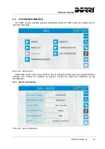
5.4.3 Parallel
information
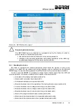
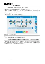
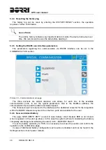
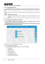
The page containing the information about the parallel is only enabled if the UPS is in parallel
with other UPSaver systems.
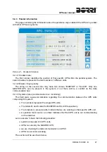
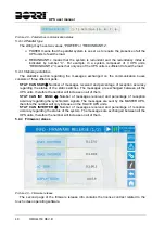
Picture 47 – Parallel information
5.4.3.1 Parallel index
The first number identifies the position of that specific UPS within the parallel system. The
second number represents the total number of UPSaver units.
5.4.3.2 Master / Slave priority
The string on the second line may have two values, “MASTER” or “SLAVE”. Only one
MASTER UPS can be present in the system; if not there will be a conflict on the data
communication bus.
5.4.3.3 System status (communication bus monitoring)
This field gives a general indication regarding the communication between the UPS units
composing the system.
The numbers represent the single UPS units.
The letters M and S stand for MASTER and SLAVE respectively.
The brackets [ ] around a letter indicate that we are working on that specific UPS unit.
A question mark next to a number indicates that that UPS unit is not communicating
on the data bus.
Let us assume to have the following situation:
system composed of 4 UPS units;
UPS2 is currently the MASTER UPS;
we are checking the data communication on UPS3;
UPS4 is not communicating.
The section will be as shown below.
Summary of Contents for UPSaver 1000 kVa
Page 2: ...UPS OPERATING MANUAL UPSaver 400 1600 kVA ...
Page 5: ......
Page 7: ...Warnings and general information 2 OMH44148 REV A ...
Page 13: ......
Page 20: ...UPSaver installation and start up OMH44149 REV C 7 ...
Page 33: ...UPSaver installation and start up 20 OMH44149 REV C Picture 6 Handling of the power module ...
Page 57: ...UPSaver installation and start up 44 OMH44149 REV C Picture 46 UPS cabinets upper fixing ...
Page 59: ...UPSaver installation and start up 46 OMH44149 REV C Picture 49 Power module cables terminals ...
Page 115: ...UPS user manual 6 OMH44150 REV B ...

