UPSaver
installation and start-up
42
OMH44149 REV. C
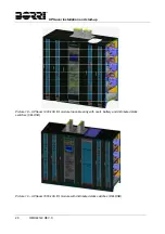
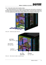
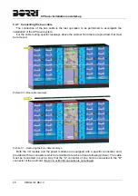
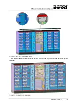
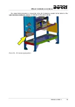
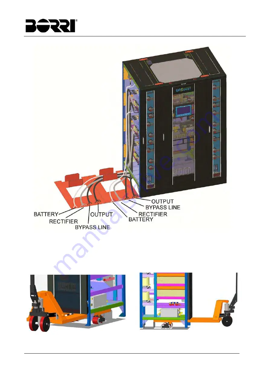
Picture 42 – Routing of the interconnection cables
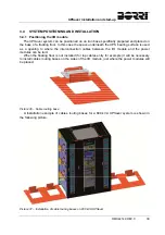
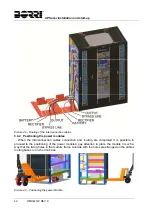
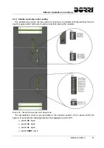
3.4.4 Positioning the power modules
When the interconnection cables connection and routing are completed it is possible to
proceed to the positioning of the power modules; pay attention to place the module in such a
way that the fixing holes in the module frame coincide with the holes prearranged on the cables
routing bases or on the iron base.
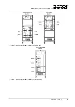
Picture 43 – Positioning the power module
Summary of Contents for UPSaver 1000 kVa
Page 2: ...UPS OPERATING MANUAL UPSaver 400 1600 kVA ...
Page 5: ......
Page 7: ...Warnings and general information 2 OMH44148 REV A ...
Page 13: ......
Page 20: ...UPSaver installation and start up OMH44149 REV C 7 ...
Page 33: ...UPSaver installation and start up 20 OMH44149 REV C Picture 6 Handling of the power module ...
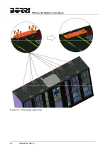
Page 57: ...UPSaver installation and start up 44 OMH44149 REV C Picture 46 UPS cabinets upper fixing ...
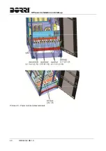
Page 59: ...UPSaver installation and start up 46 OMH44149 REV C Picture 49 Power module cables terminals ...
Page 115: ...UPS user manual 6 OMH44150 REV B ...

