UPSaver
installation and start-up
OMH44149 REV. C
45
3.4.6 Power modules electrical connection
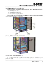
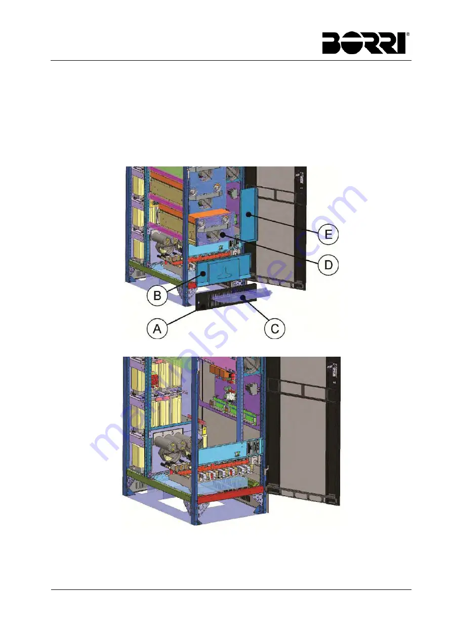
In order to connect the interconnection cables of the power module it is necessary to remove:
front socket cover (A);
terminals protection plate (B);
cables passage covering plate (C).
In order to ease cables connection work it is advisable to remove the lower power conversion
module (D) and the side protection plate (E).
Picture 47 – Parts to be removed for cables connection
Picture 48 – Power modules with parts removed
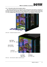
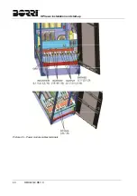
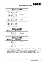
The connection terminals are available on the front of the cabinet and located as shown in
the following picture.
Summary of Contents for UPSaver 1000 kVa
Page 2: ...UPS OPERATING MANUAL UPSaver 400 1600 kVA ...
Page 5: ......
Page 7: ...Warnings and general information 2 OMH44148 REV A ...
Page 13: ......
Page 20: ...UPSaver installation and start up OMH44149 REV C 7 ...
Page 33: ...UPSaver installation and start up 20 OMH44149 REV C Picture 6 Handling of the power module ...
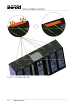
Page 57: ...UPSaver installation and start up 44 OMH44149 REV C Picture 46 UPS cabinets upper fixing ...
Page 59: ...UPSaver installation and start up 46 OMH44149 REV C Picture 49 Power module cables terminals ...
Page 115: ...UPS user manual 6 OMH44150 REV B ...

