7
Digital Multimeter
Intended Use
The multimeter is suitable for measuring:
• Direct voltage (VDC, voltage of accumulator or battery,
for example)
• Direct current (ADC)
• Alternating voltage (VAC, voltage of the mains input of a
device, for example)
• Resistance (Ω, Ohm)
• Diodes and hFE transistor measurement
• Alternating current (AAC)
• Continuity test
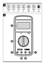
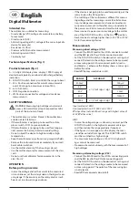
Technical specifi cations (fi g. 1)
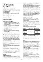
Product elements (fi g. 2)
A – 3,5-digit LCD display (max. display: 1999. Display of
decimal point, polarity, overload and discharged battery
indication.
B – FUNCTION switch: Rotary switch for the range to beset
C – 20 A. Positive connection for current measurements
over 200 mA up to a maximum value of 20 A.
D – mA. (0-200 mA)
E – COM. Negative connection.
F – VΩ. Positive connection for voltage and resistance
measurements.
SAFETY WARNINGS
WARNING! Measuring high voltages and currents
poses a life hazard. Never touch exposed metallic
parts of the instrument leads.
• The multimeter is sensitive. Protect it from vibrations
and do not let it fall down.
• If the multimeter is not going to be used for a time,
please switch it OFF to save on batteries.
• If the multimeter is not gong to be used for a long pe-
riod, remove the battery in order to avoid spilling.
• Do not subject the device to high humidity or high
temperatures.
• Keep the multimeter away from strong magnetic fi elds.
• Remove the instrument leads immediately if you smell
burnt cable insulation.
• Use the multimeter only if the housing is closed.
• Use the multimeter only for measurements of the class
I or II.
• Do not use the multimeter for measurements in the
class III or IV.
OPERATION
Before putting in service
• In case the voltage and/or the current to be measured
is/are unknown, set the rotary knob on the largest meas-
uring range. If the accuracy on the rotary knob is insuf-
fi cient, set on a lower range and soon.
• If the device is not going to be used temporarily, put the
rotary knob in the OFF position.
• The switching of the multimeter is diff erent for measur-
ing voltage and for measuring current. Parallel connec-
tion in voltage measurement and series connection in
current measurement. In the latter case, a conductor in
the power circuit to be measured must be interrupted.
• Never connect a power source or voltage to the multim-
eter, if the FUNCTION switch is in the Ω or
position.
• Never connect a voltage higher than 1000 V DC or 750 V
AC to the measuring device.
Measurements
Measuring direct voltage (V DC)
• Connect the BLACK lead to the «COM» connector socket
and the RED lead to the «VΩmA» connector socket.
• Set the FUNCTION switch on the desired «V» setting and
connect the leads to the voltage source to be measured
or measuring points. Observe correct polarity (red is +
and black is -), otherwise the display shows a minus sign
before the value.
• Read off the measured value in Volt.
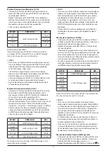
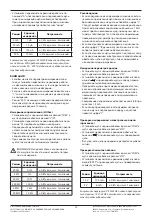
RANGE
ACCURACY
RES.
200 mV
± 1,5% of rdg ± 1 dgt
100 μV
2 V
1m V
20 V
10m V
20 V
100m V
1000 V
± 1,5% of rdg ± 2 dgt
1 V
Input resistance 10 MΩ
Overload protection DC 1000 V or AC 750 V
Eff ective value (outside 200-mV-range with highest value of
250 V Eff ective value).
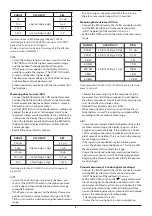
HINT:
• In case the voltage range is unknown, you must put the
FUNCTION switch in the highest measurement range
and then reduce the range gradually if required.
• If the fi gure «I» now appears on the display, the meas-
urand lies outside the range set. The FUNCTION switch
must be switched to a higher range.
• The maximum input voltage is 1000 V DC. Higher volt-
ages cannot be measured.
• Proceed extremely cautiously with the measurement of
high voltages.
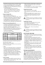
Measuring alternating voltage (V AC)
• Connect the BLACK lead to the «COM» connecting point
and the RED lead to the «VΩmA» connecting point.
• Set the FUNCTION switch on the desired «V» setting and
connect the leads to the voltage source to be measured
or measuring points. The polarity of the measuring tips
is not relevant.
• Read off the measured value in Volt.
English
Summary of Contents for 91271143
Page 2: ...3 1 0 1000 V 0 750 V 0 20 A 0 20 A 0 3 kg 0 200 F 0 20 M 2...
Page 16: ...17 RU FR DE GB Garantiebedingungen Warranty terms Conditions de garantie...
Page 22: ...23 BORT GLOBAL LIMITED BORT GLOBAL LIMITED 2 Defort 5 SDS BORT GLOBAL LIMITED GmbH 21 10719...
Page 26: ...30...
Page 27: ...31...


