13
Simply connect the LE300 system directly in parallel to the lead acid battery at
the RAST 5 (code 00E) power connector . Therefore, use the supplied plug con-
nector, fix cables to it, plug it to the back of the LE300 at the power connector
.....
and mount the other side of the cables to your lead acid battery. Pay attention to
right polarity and proper cable connection!
Check if the 20 A fuse is inserted at . If fuse is missing, insert the supplied
spare part 20 A fuse.
In case of parallel connection of several LEs, make sure that LE enclosures are
mounted firmly together. It is recommended to use a threaded bolt and nuts
to tighten LEs with each other (optional mechanical parallel mounting kit). It is
recommended to connect all LE300 with each other through RS485 communi-
cation and . LE300s would also work in parallel mode without the RS485
communication, however one common state-of-charge-trend-signal couldn’t be
generated anymore for the whole system. Maximum number of LEs in parallel
configuration is 24 LEs as standard version, please get in touch with your BOS
dealer if more LEs in parallel are needed.
Optional signal outlet for display connection. 0 - 10 V state-of-charge-trend-
signal to be connected to displays with 0 - 10 V signal input. It is recommended
to use the following plug with cables at the signal outlet: Mini-Fit Jr.™ TPA Cable
Assembly 45135 (plug not included). Optionally a LCD state-of-charge-trend-dis-
play is available.
ANOUT
Analog
Out
1
3
2
4
GND
Ground
DIN1
Digital
Input 1
DIN2
Digital
Input 2
Pin
1
2
3
4
Name
Anout
DIN1
DIN2
GND
Description
Analog OUT 0 - 10 V
SOC (0 V = 0%
10 V = 100%)
Digital IN 1
(Wake up)
Digital IN 2
Ground
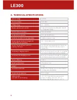
Display out graphic


