1 689 989 245
2015-04-28
|
Robert Bosch GmbH
18 | 0 986 610 825 | Initial commissioning
en
4. Initial commissioning
4.1
Tool case 0 986 613 930
Placing the tools:
Place the tools in the provided foam inserts as
shown in the enclosed position diagram.
4.2
Shim case 0 986 613 940
Placing the storage tine 0 986 610 546:
1.
Attach identical stickers to the cover and body of the
tin.
2.
Place the storage tins in the case as shown in the
position diagram (color-coded).
3.
Affix the position diagram to the inside of the case
cover.
"
The storage tins are now ready for placing the shims
in them.
i
Apply a film of oil to the shims to prevent corrosion
prior to storing them.
4.3
Measuring insert for digital dial
gauge 0 986 613 422
Attaching the measuring insert
1.
Remove the attached probe (right-hand threads)
from the measuring pin of the dial gauge.
2.
Screw measuring insert 1 683 521 101 into the
measuring pin of the dial gauge by hand as far as
possible.
3.
Press the measuring pin of the dial gauge back as far
as possible and hold it in place.
4.
Place a piece of leather or cloth around the knurling
on the measuring insert.
5.
Using a pliers, grasp the cloth around the knurling
on the measuring insert and tighten the insert slight-
ly with a clockwise motion.
"
The measuring insert is now connected to the mea-
suring pin securely and without play. This prevents
incorrect measurements.
4.4
Installing the mounting unit
0 986 610 897
Wear eye protection
Wear safety shoes
i
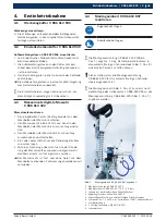
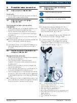
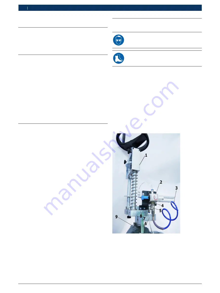
Mounting unit 0 986 613 400 (fig. 1, item 1) weighs
approx. 24 kg. For this reason, have a second person
assist when placing it in the workshop vise (fig. 1,
item 9).
!
Make sure that the mounting device 0 986 613 400
is clamped securely in the workshop vise.
i
The mounting unit (fig. 1, item 2) cannot be at-
tached until conversion kit 0 986 613 393 has been
installed on mounting device 0 986 613 400 (fig. 1,
item 1).
Fig. 1:
Mounting unit 0 986 610 897 attached
1 Mounting device 0 986 613 400
2 Mounting unit 0 986 610 897 (5.0 – 5.5 bar)
3 Line from workshop's compressed-air system
4 Coupling connector; nominal diameter 10 mm
5 Compressed-air connection to workshop's compressed-air sys-
tem
6 Hose 10 x 1.5 x 450 mm; polyurethane (PUN), calibrated outside
7 Connector
8 2 x Cheese head bolt; M5X8 (DIN912)
9 Vise

